
When to use this procedure
Under normal circumstances, firmware updates are done through the controller's own software. Use this recovery procedure only when the controller is truly bricked—no LED blinking at all—typically after a failed update left it unresponsive.
Step 1—erase the microprocessor

Remove all peripherals and open the controller box (4 screws). Inside, locate the recovery USB plug and a pair of pins provided for this procedure. With the controller powered—either from its power supply or via the recovery USB connection to a computer—short these two pins together. This erases the microprocessor back to its factory state. Once done, unpower the unit—remove the USB cable or the power supply.
The box screws are easy to spot on the Dragonfly and on the aluminium-box Armadillo; on all other models they are hidden behind four caps.
Step 2—install SAM-BA
Download the SAM-BA package, then run the installer. On the final installation screen, leave the USB notice option checked—it walks you through the driver setup covered next.

Step 3—fix the USB driver
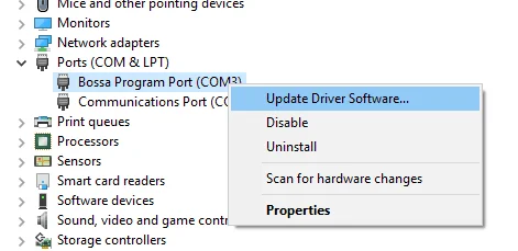
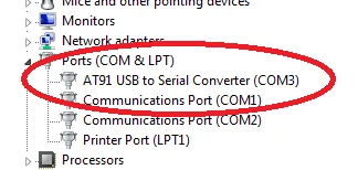
Connect the erased controller via the recovery USB port. Windows may first recognise it as a "Bossa Program Port"—this is not correct for SAM-BA. Open Device Manager, right-click that port, choose Update Driver Software, and point it to Atmel's official driver folder:
- 32-bit Windows:
c:\Program Files\Atmel\sam-ba_2.16\drv - 64-bit Windows:
c:\Program Files (x86)\Atmel\sam-ba_2.16\drv
Step 4—connect in SAM-BA
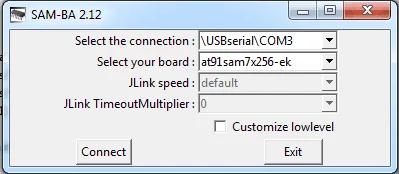
Launch SAM-BA and set two fields:
- Connection:
\usb\ARM0or\USBserial\COMn(the exact ARM/COM entry will vary). - Board:
at91sam7x256-ek—select this one exclusively; anything else will prevent the recovery from working.
Step 5—flash the bootloader
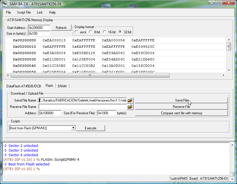
In almost every case you will now reach the SAM-BA main window:
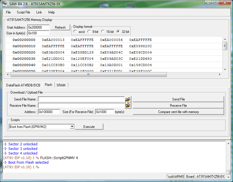
Open the Flash tab, click the folder icon next to Send File Name and select the bootloader file for your controller—download the one matching your model:
- Original Seletek:
BLSeletek.bin - Armadillo (any model):
BLArmadillo.bin - Platypus (any model):
BLPlatypus.bin - Dragonfly:
BLDragonfly.bin
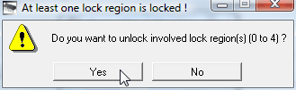
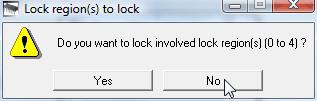
Click Send File. On very old controllers you may see a lock-region warning—confirm with Yes to unlock. If SAM-BA then asks whether to re-lock the region, answer No: no memory region should remain locked.
Step 6—boot from flash
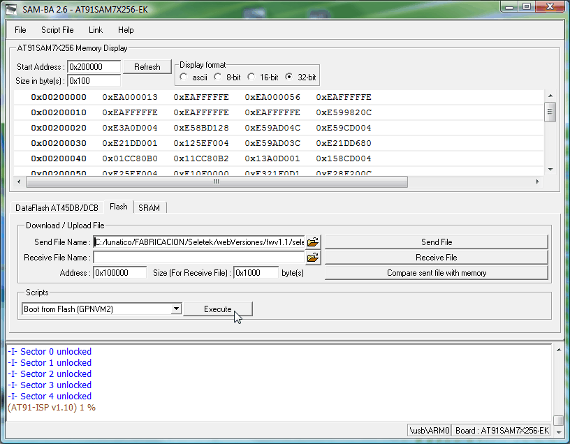
Once all sectors show as unlocked, select the script "Boot from Flash (GPNVM2)" from the Scripts dropdown and click Execute. This completes the bootloader installation.
Step 7—reinstall the operative firmware
Power cycle the controller and reconnect it via its normal USB or network connection. Drag and drop the current operative firmware file onto the software:
- Original Seletek:
seletek.bin - Armadillo (any model):
armadillo.bin - Platypus (any model):
platypus.bin - Dragonfly:
dragonfly.bin
For network-enabled controllers, the factory default address is 192.168.3.67 if DHCP is not available.
Once your controller is up to date you can safely uninstall Atmel's program and close the controller box.
Why this works: every controller carries two separate firmware layers—a bootloader (only active during a recovery like this one) and the operative firmware (what runs day to day). This two-layer design is what lets the normal firmware update be a simple drag-and-drop, while still leaving a low-level recovery path when something goes wrong.