
1. Introduction
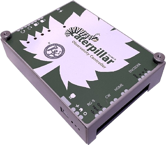
The Caterpillar Family comprises a number of roof and dome products. You’re currently looking at the manual for the CaterpillarR (the relay model). If this is not the one you’re after, please check the Caterpillar page on our website!
All Caterpillars are fully compatible with the Lunático CloudWatcher and other monitors, such as Hydreon’s rain gauges. They are aimed at manufacturers and system integrators, and DIY-oriented astronomers.
The CaterpillarR is capable of driving 3-phase, DC, and stepper motors (with external drivers). It works with a single board, and is ASCOM-compatible.
1.1. Elements
The CaterpillarR is the Caterpillar model that works with relays (hence the R). For observatory domes designed to be manually operated by four buttons (to open the shutter, close it, rotate clockwise and rotate counter-clockwise), the CaterpillarR automates these functions via four relays, wired in parallel with the buttons on the control unit.
The four buttons must not directly power the motor for this to work. Specialised switches or a VFD, configured to control the motor via the VFD’s inputs, can be used to control the motor (more on this, including diagrams, in the setup section).
Rotation of the dome is measured by a rotary encoder, and the home position is confirmed by a proximity switch. The combination of these allows for very precise positioning of the dome.
Opening and closing of the shutter is assumed to happen in a period of time - not position feedback is supported in this version.
1.2. Assembly
The manufacturer / integrator will be responsible for assembling their own setup, using a caterpillar and a few other components—depending on the selected motor control. Lunático will provide the necessary diagrams for the entire assembly, as well as technical support where necessary.
There is always a real risk when dealing with electrical circuits. Seek assistance if needed and comply with your local regulations. The responsibility is yours.
2. Setting up the hardware
2.1. Wiring everything up
Let’s start by wiring up all the elements that are going to be part of our setup into the CaterpillarR. Here you have a connections diagram, but we’ll go item by item below. Note the right side of the board (as depicted) is devoted to inputs (home sensor, encoder, etc) while the left one is the control / output side.
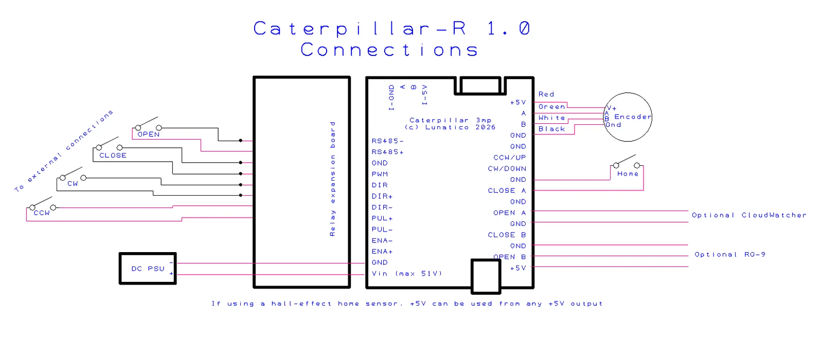
Click on the image to be redirected to the original, full-size one. More diagrams are available below, including for a hall-effect home sensor.
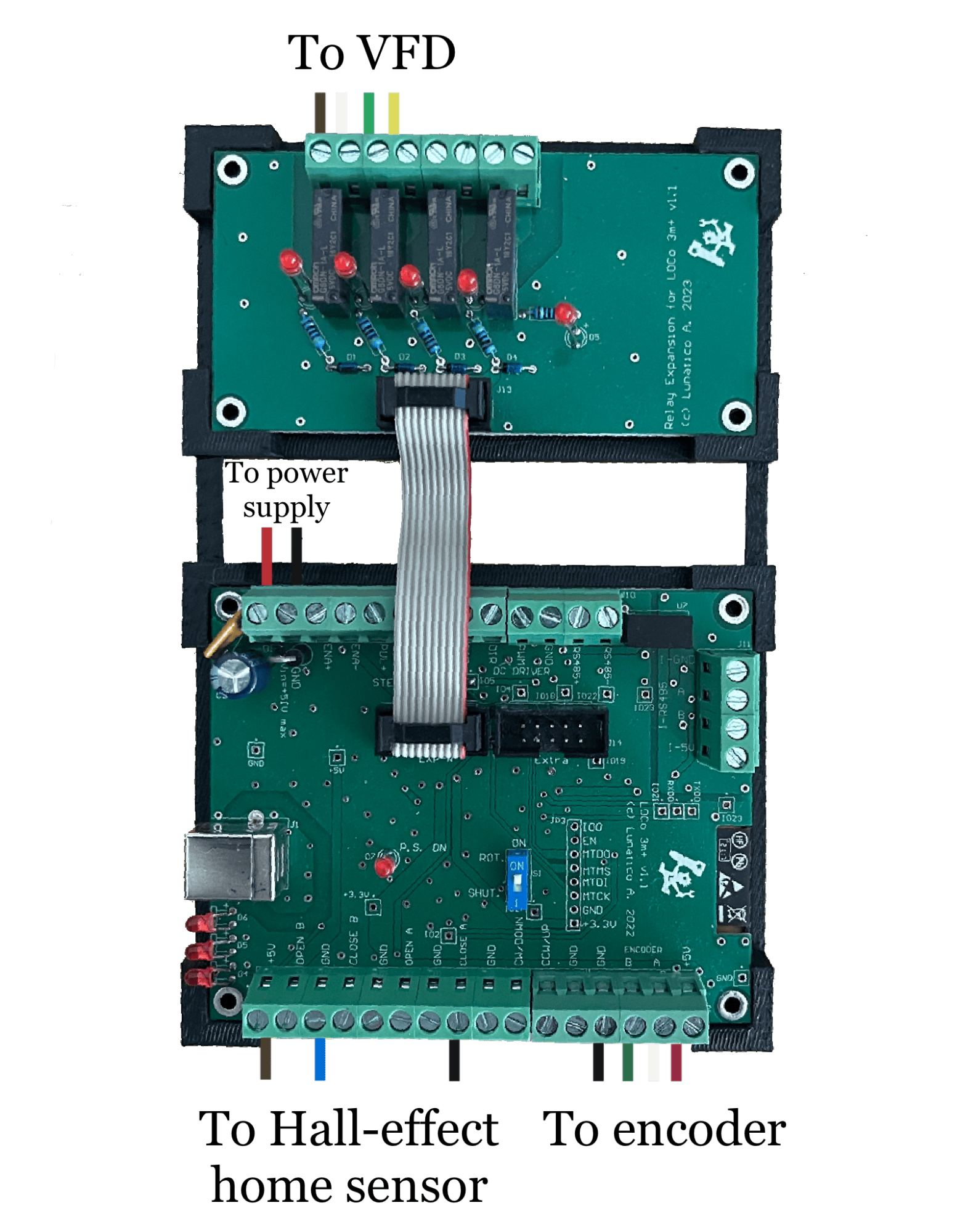
CaterpillarR connections example
2.1.1. Home sensor
The rotation unit needs a home sensor. Both a mechanical or a hall-effect sensor (usually preferred) can be used. They are wired to the same connector on the board, which provides +5 V required for the hall-effect one.
In normal operation, should the home sensor not be found after a complete revolution, the system will stop and issue a warning.
Hall-effect sensor (preferred)
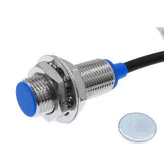
Popular NPN hall-effect sensors include an LED that will light when the sensor is active, which is very convenient to test the system during installation.
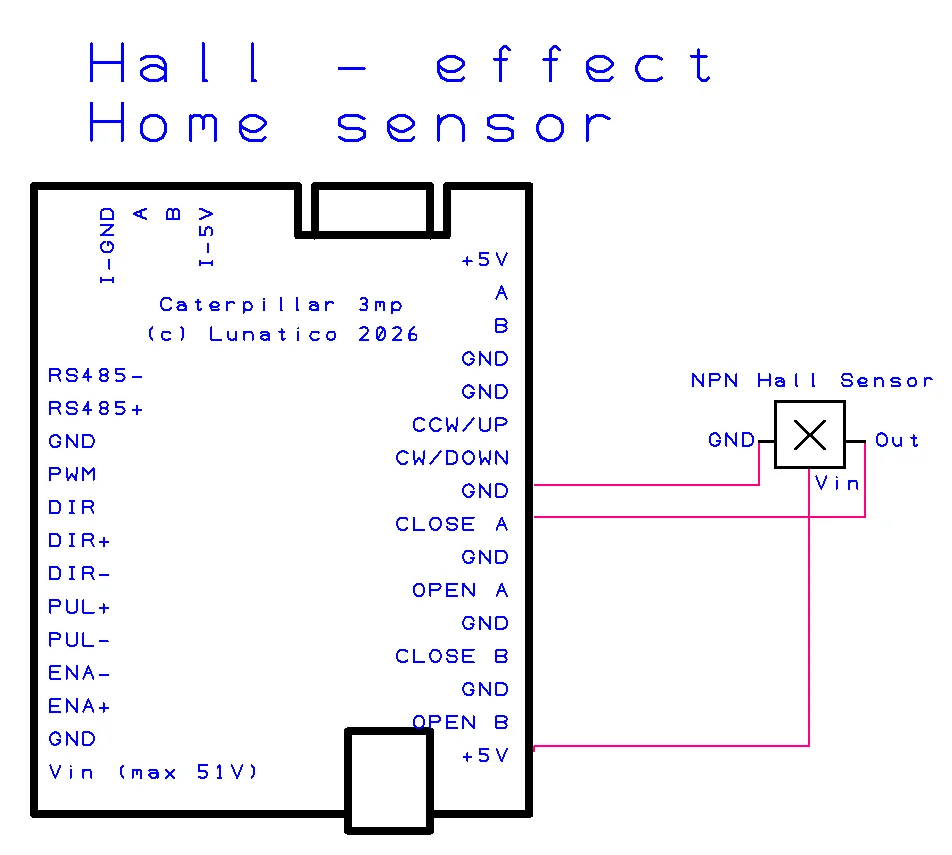
Hall-effect (NPN) sensor wiring
Tested Hall-effect sensor
One sensor we have tested to work with the +5 V from the Caterpillar board is the NJK 5002C.
Mechanical home switch
A normally open mechanical push-button or lever switch can also be used. For switches with two closed positions (i.e. the lever can be pressed from either side), precautions must be taken so it is only triggered at one point per revolution. A good approach is placing the sensor horizontally, so the dome lowers the switch when reaching the home position, rather than pushing it sideways—this way only one consistent trigger point is possible.
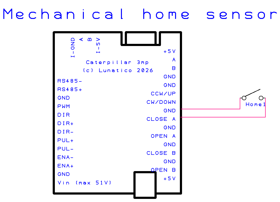
Mechanical limit switch wiring
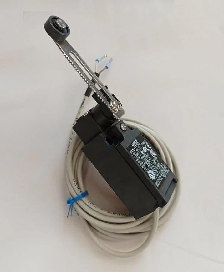
This Omron sensor is an example of mechanical sensor with 2 closed positions; horizontal mounting avoids double-triggering
2.2. Encoder
Rotation of the dome is measured by a rotary encoder, and the home position is confirmed by the home sensor. The combination of these allows for very precise positioning of the dome.
The encoder is required; without it, the system cannot track dome position accurately. If the encoder does not detect motion when the dome is running, the system will stop and issue a warning.
The encoder can be coupled either to the motor axle—downstream of any reduction gearing—or directly to the dome rack, using a dedicated coupling. A non-friction coupling is preferable in either case, to avoid slippage.
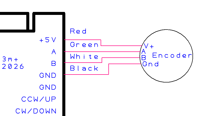
Encoder wiring
Encoder specs
NPN, 5V DC quadrature encoder required. The system will track up to 2 KHz step pulses, which is clearly overkill. Anything above a few counts per degree will provide ample resolution for dome tracking.
2.3. Power supply
The power input accepts from 12 up to 51 V DC; the board provides a regulated +5 V output for powering sensors. It will draw about 500mA max at 12V DC.
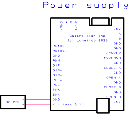
Power supply connection diagram
3. Setting up the software
You will need to have downloaded and installed the ASCOM platform (available from here). You will also need to install the Caterpillar’s software and its USB drivers.
The Caterpillar’s software includes the ASCOM driver and is available from this link. It has two components, the dome driver and a safety monitor for the optional weather input (recall that a CloudWatcher can be used for this purpose).
The Caterpillar’s USB drivers can be found at this link.
3.1. Plugging in for the first time
Connect your computer to the CaterpillarR with the provided USB cable, and turn the CaterpillarR on (i.e. supply power to it). Windows will detect a new device and load the correct drivers automatically.
In order to find out which COM port has been assigned to your CaterpillarR, use the Windows Device Manager—this number will always be the same for your device, and will be required to configure the connection. You should also disable the power saving feature of the USB port.
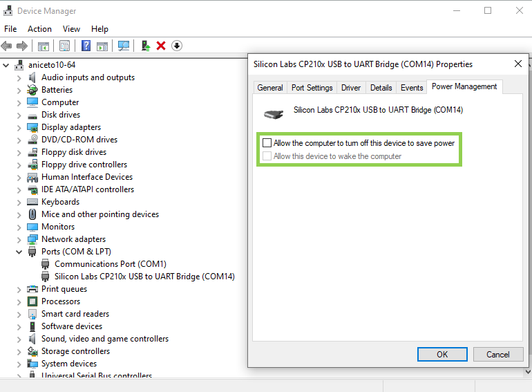
3.1.1. Calibrating from the ASCOM Driver
- Launch your dome control program, ASCOM Device Hub in this example—run it from the ASCOM menu (Start Menu → ASCOM platform 6).
- Select the menu Tools → Setup.
- Select the Dome Setup tab.
- Select Caterpillar ASCOM driver.
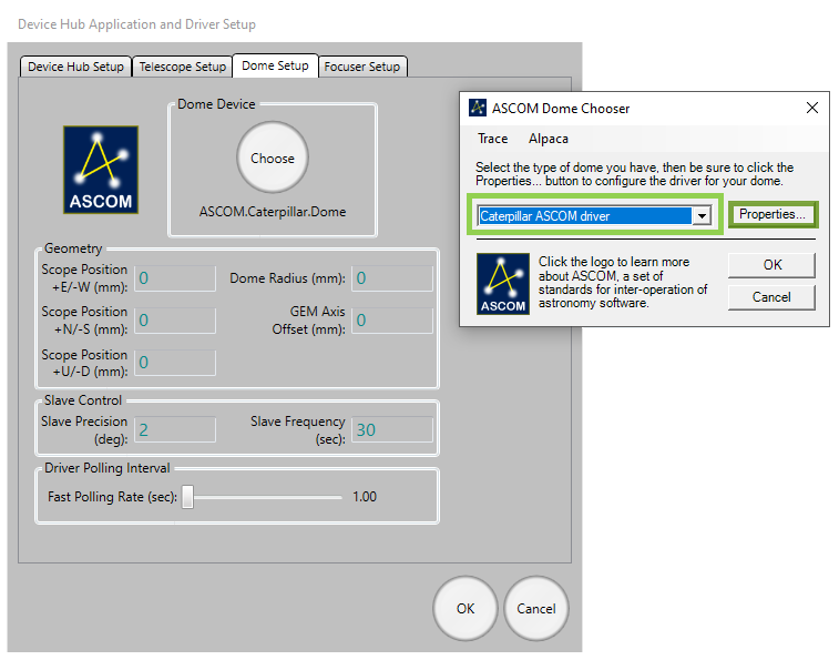
Click on Properties, to open the Caterpillar Setup window.
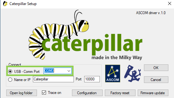
From the USB - Comm Port dropdown menu, select the port number associated with the dome rotation unit USB port connection identified earlier in the Device Manager. Then press Configuration.
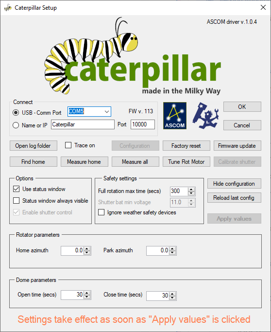
The second row of buttons allow to calibrate the Caterpillar. You will need to run Tune Rot Motor and then Measure all.
Find home | drives the dome until it locates the physical home sensor. |
Measure home | finds the home sensor, then sweeps back and forth across it to precisely measure its trigger point from both directions. Usually not needed. |
Measure all | measures the full circumference together with the home sensor; the complete calibration. |
Tune Rot Motor | matches the motor to the encoder. |
Calibrate shutter | not applicable to the CaterpillarR. |
Want a breakdown of this window and the rest of the settings? Please head to the Advanced Configuration section!
The CaterpillarR must be calibrated (firstly running Tune Rot Motor, and afterward running Measure all), before the first use and after a factory reset has been carried out; also if there are mechanical changes*.
*by this we mean if you change the motor, the encoder’s coupling, if CW and CCW had been connected the wrong way around, etc.
If the above steps complete successfully, your system will now be ready to operate.
- Click OK on this window, and then again on the Dome Setup window.
- Select the Dome tab on the ASCOM Device Hub window, and click Connect Dome.
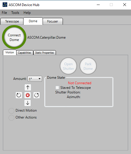
Congratulations; you can now control your dome via any ASCOM compatible Windows software!
3.1.2. Synching the telescope and the dome
Some programs, such as Voyager or Sequence Generator Pro, include their own dome to telescope slaving. It is up to you to choose the software to synchronise both elements. The ASCOM Device Hub is used here for reference.
First off, set up the telescope driver, analogously to how you just set up the dome. Afterward, follow these steps:
- Select the menu Tools → Setup.
- Select Telescope Setup and select your telescope model, and confirm pressing OK.
- To slave the dome to your telescope, check the Slaved to telescope option box.
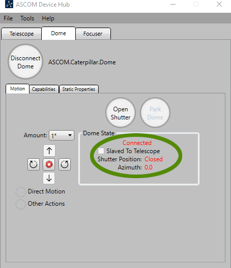
Your dome will be following your telescope from now on!
It would be a good idea to test your system now by checking the shutter operation and that the rotation buttons also operate correctly. If everything is working correctly, disconnect the dome from the ASCOM Device Hub and go to the Dome Setup page for more dome geometry and other configurations.
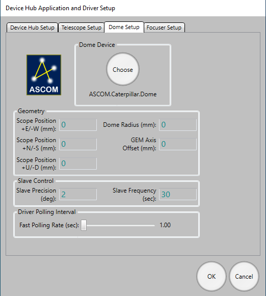
Unless the telescope rotation is perfectly centred on the dome and uses a fork mount, it will be necessary for the software to correct for the misalignment of the axis. This can be done in the geometry section, specifying the values for each misalignment:
- E/W → for the typical pier, at the centre of the dome this value will be 0.
- N/S → for German Equatorial Mounts, there will be some North (for the Northern Hemisphere) or South (for the Southern Hemisphere) displacement, increasing as the distance from the equator does.
- Up/Down → the displacement of the telescope rotation point from the centre of the dome sphere.
For each value, we’ll see a window to adjust it:
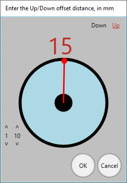
Other geometry values:
- Dome Radius.
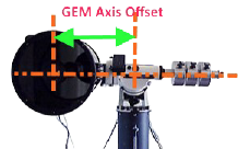
- GEM Axis Offset → length of the distance between the RA axis and the centre of the telescope. For fork mounts, this will be 0.
The remaining configuration parameters are:
- Slave precision → the margin for error, which decreases with increasing telescope aperture. The default value is 2 degrees.
- Slave frequency → how often the alignment will be checked. The default setting is every 5 seconds.
- Driver polling interval → how often the Device Hub will contact your Caterpillar. The default setting is every 2 seconds.
Geometry measurements explained
In order to synchronise your dome with a telescope, you must provide information about the telescope geometry and how it’s positioned within the dome.
The computations required for scope-dome synchronisation are non-trivial and somewhat sensitive to small input errors. Therefore, to get accurate scope-dome synchronisation across the whole sky, your geometry settings must be as accurate and precise as possible.
The meaning of each setting will be explained in detail, but first a note about origins.
The scope position offset is the amount by which the telescope’s centre of rotation is offset from the centre of the dome’s rotation. It is important to understand where the telescope’s centre of rotation is located. This is not necessarily over the centre pier and is, in fact, the intersection between the polar (right ascension) axis and the declination axis. In the following examples, the centre of rotation is circled in green:
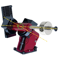

Note that the point of interest is inside a solid object! This makes measurement difficult, but it’s important that it be as precise as possible. You may need to use some ingeniousness to obtain your measurements. One possible approach is to measure the distance to the edge of the axis and then add the axis’s radius.
Similarly, the centre of rotation of your dome is an imaginary point in space. This can be found by dropping a plumb line from the centre of the roof and then registering the point along that line that is level with the top of the dome walls. This point, the dome’s centre of rotation, is the origin for all your geometry measurements.
The N/S, E/W and Up/Down parameters describe by how much the mount intersection point is offset from the centre of rotation of the dome. The best way to measure this is often by taking differences.
- First identify the four cardinal points (North, East, South, West) around the rim—remember that North is True North, not Magnetic North. You may wish to mark these points for future reference.
- Then measure the distance between the intersection point of the telescope to the north, south, east and west points of the dome rim.
- Your N/S offset is then your measured South distance minus your measured North distance. This will be positive if the offset is to the North and negative if it is to the South.

Similarly, your E/W offset is the measured distance to West minus that to East.

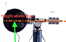
The Up/Down distance is the height of the mount’s intersection above the dome’s rim. Positive means the mount’s intersection is above the rim, negative that it’s below. One way to measure this would be to place both the declination axis and the telescope tube perfectly horizontal (using a spirit level) and measure the height above the floor of the centre of the telescope tube, or the counterweight shaft; then subtract the height of the dome’s rim to give the Up/Down offset.

The final measurement is the “GEM axis offset”, which is the distance from the intersection point to the centre of the telescope tube. Again, this can be difficult to determine as it is in the middle of a solid object. The best way to approach it may be to measure the distance from the intersection point to the top of the saddle plate, then from the saddle plate to the centre of the telescope tube (or measure the diameter of the tube and divide by 2 to get the radius), and then add them together.

Aim to be as accurate as you can in all the measurements, as the accuracy will affect how well synchronisation works. Aim for a precision of at least 1 cm, and ideally 1 mm. It is worth taking some time to get accurate results and hopefully you will only need to do this once.
3.1.3. Safety measures
The system includes several advanced safety features:
Up to two rain / weather sensors can be connected, with a normally open relay (such as the Hydreon RG9 / RG11 rain detectors, plus the Lunático CloudWatcher). In case of rain or bad weather, the system will automatically close the shutter.
- Should the home sensor not be found after a complete revolution, the system will stop and issue a warning.
- If the encoder does not detect motion, the system will stop and issue a warning.
Please note that this system does not include open and close limit switches (they can be fitted optionally). The opened or closed status is assumed after operating the buttons for the configured time.
3.1.4. Advanced configuration
The CaterpillarR’s default settings cover most observatory set-ups. However, if you want to change these settings or preferences, you can do so by clicking on Properties on ASCOM Device Hub, Setup → Dome Setup window. This will open the CaterpillarR Setup window, and from there if you click on Configuration, you’ll end up on this window, which we discussed earlier.
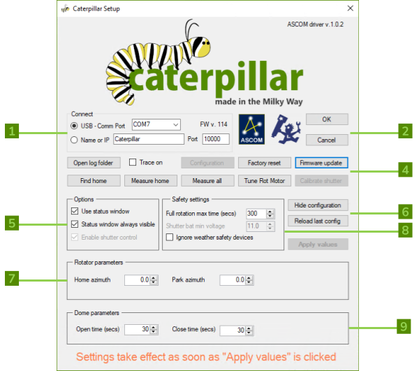
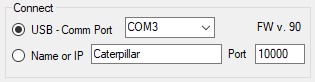
Connect:
Shows how the CaterpillarR is connected to your observatory computer.
OK / Cancel:
Select OK to confirm or Cancel to discard changes.

- Firmware:
- Open log folder: opens the folder where the system log is stored (to enable logging, tick the Trace on box).
- Trace on: select this option if you are encountering problems (the log will be saved in the folder accessible by the Open log folder button).
- Factory reset: returns the CaterpillarR to its default settings and erases the calibration.
- Firmware update: firmware can be updated from the internet or from a downloaded file.

- Calibrations:
As mentioned above, the CaterpillarR must be calibrated (firstly running Tune Rot Motor, and afterward running Measure all), before the first use and after a factory reset has been carried out.
- Find home: moves the dome to the home position, and checks that the sensor is active.
- Measure home: rotates the dome until the home sensor is found, and then carefully measures its size, so that in future an accurate synchronisation can be made.
- Measure all: determines the home position and performs a full rotation until the same point is reached again, then measures the home sensor size as above.
- Tune Rot Motor: exercises the rotation motor a few times while checking the encoder to be able to execute precise go-to operations.
- Calibrate shutter: not applicable to the CaterpillarR.

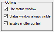
- Options:
- Use status window: displays some information and controls. If checked, it will pop up on your screen every time the CaterpillarR is active.
- Status window always visible: keeps the Status window visible, on top of other windows.
- Enable shutter control: always enabled in the CaterpillarR (even if you don’t have a shutter, this is fine and can be ignored).
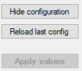
- Configuration settings:
- Hide configuration: removes the configuration display.
- Reload last config: reloads the last saved configuration.
- Rotator parameters:
- Home azimuth: the physical position of the home sensor (in degrees).
- Park azimuth: specifies where the dome will point when not in use (in degrees). Upon power-up, it will be assumed to be in this position.

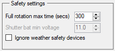
- Safety settings:
- Full rotation max time: the maximum time the dome can be rotating with no home sensor detection. If exceeded, the system will stop and signal an error.
- Shutter bat min voltage: not available in the CaterpillarR.
- Ignore weather safety devices: disable hardware inputs from external weather safety devices.
- Dome parameters:
—Open / Close time: specifies the time the relays have to be activated to ensure a complete open or close operation.
