
There are 2 options:
- A) If you don't have the Hydreon rain sensor.
- B) If you already have the Hydreon rain sensor.
What's supplied
A) If you don't have the Hydreon rain sensor:
- Bottom part of the CW box—adapted for the Hydreon sensor.
- Hydreon sensor, CW-ready.
B) If you already have the Hydreon rain sensor:
- Bottom part of the CW box—adapted for the Hydreon sensor.
- 3-wire cable with a special terminal block.
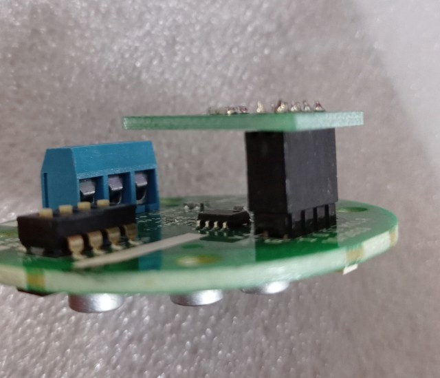
- PCB to connect to the Hydreon sensor.
Step 0, as a precaution: take a picture of the PCB and cables with your smartphone. May come in handy in case of troubles.
A) If you don't have the Hydreon rain sensor
To connect the PCB to the supplied base:
- Disconnect all cables from the original CW.
- If your unit has an external humidity sensor, you'll have to remove it and reattach it to the new box.
- Place the PCB in the box, fix with 2 screws, and reconnect all cables as in the image below:
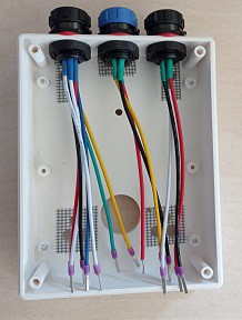
- Cut and discard the capacitive rain sensor cables—cut them short to avoid them touching the board.
- If you removed your external RH sensor, you'll have to attach it again now.
- The new Hydreon rain sensor uses the following connections:
- Red cable → 5V (in the IR sensor / RH sensor block)—so you may end up with up to 3 cables in the +5V terminal.
- Yellow cable → Cap
- Black cable → GND
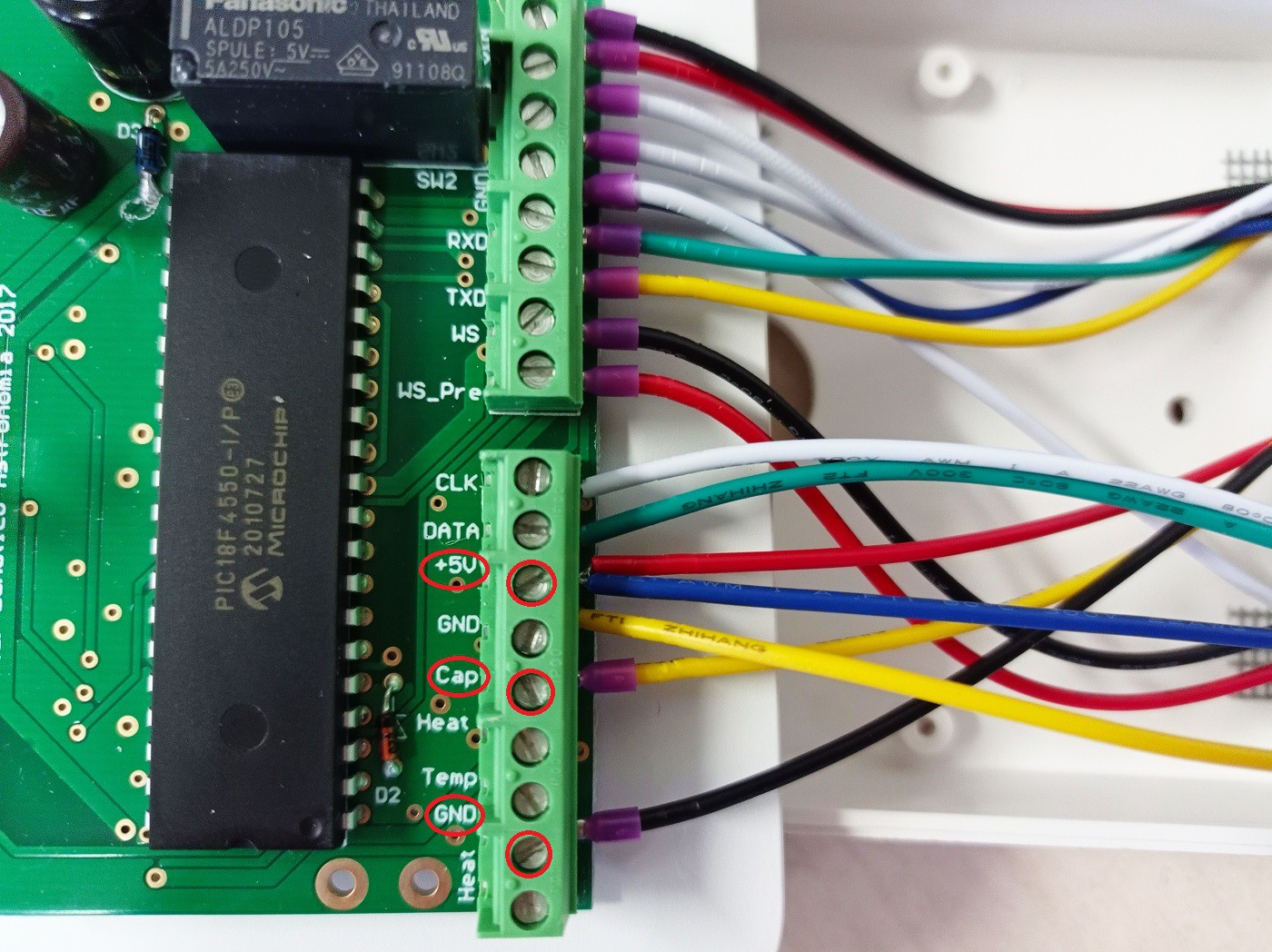
- Close the box—your Hydreon rain sensor is ready to be connected to the IP68 socket.
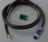
B) If you already have the Hydreon rain sensor (RG-9 or RG-15)
There's an extra step—you have to get it ready for the CloudWatcher:
- Remove the 4 bottom screws of the rain sensor.
- Insert the supplied 3-wire cable using the central hole.
- Solder the supplied board to the cables:
- Black wire → GND
- Red wire → V+
- Yellow wire → OUT
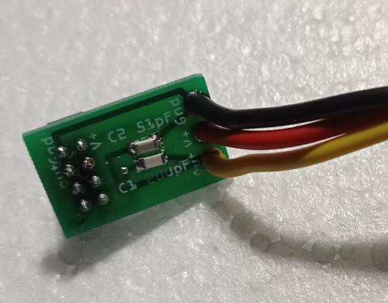
- Connect the PCB to the Hydreon board:
- Close the Hydreon again—it is now as if it was supplied by Lunático.