We have spent twenty years building instruments that run outdoors, unattended, with nobody there to restart them. That work is useful well beyond the field we started in. The boards on this page are meant to be built into someone else's automation, monitoring or control system, and to keep working when the weather turns.
We are a small company. The person who answers your email designed the board and the firmware, and is the one who will change it if your application needs something different.
Our instruments run unattended at universities, research institutes and companies in both hemispheres, several of them on sites that are difficult to reach and more difficult to service.
Both products on this page exist because a customer described a problem we had not been asked for before. We design to the requirement: a different interface, a different measurement range, another form factor, your connector, your enclosure.
If what you need is close to one of the two below but not quite it, tell us. That is usually where these projects start.
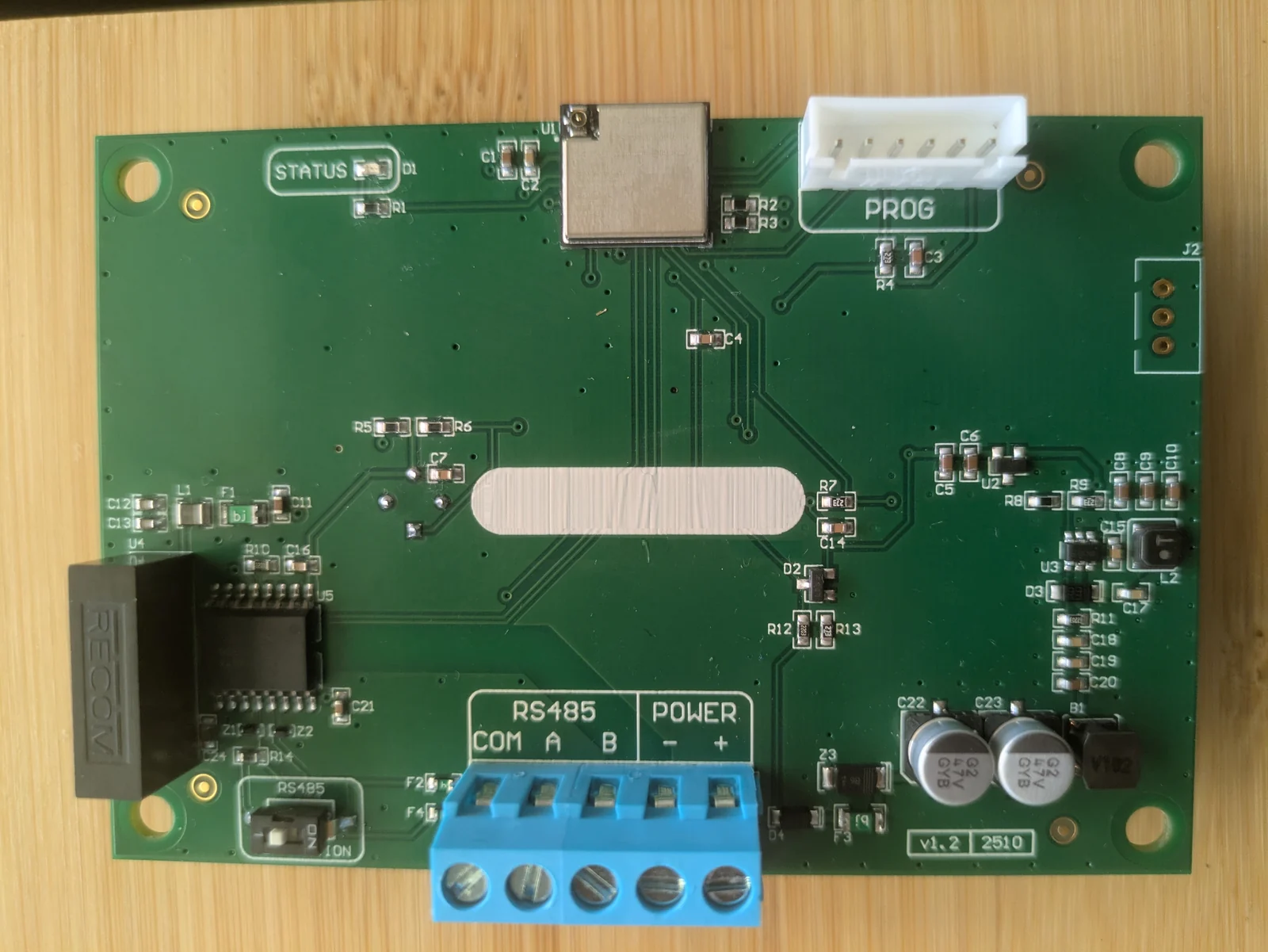
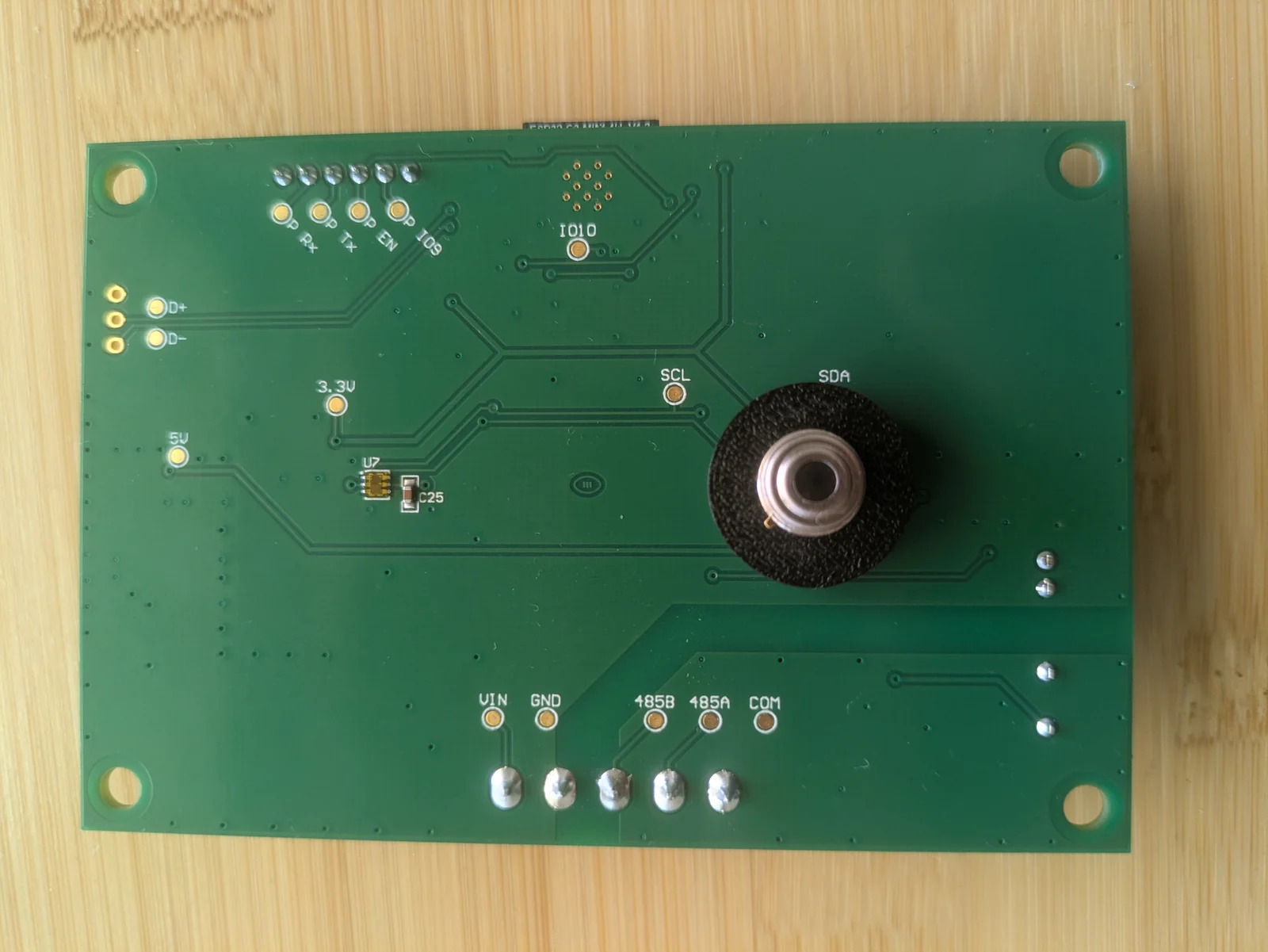
An industrial cloud and ambient light sensor. It answers two questions continuously and without supervision: how much cloud is overhead, and how much light there is—the second in lux. It reports both over RS-485 using Modbus RTU, which means any PLC, SCADA front end, gateway or data logger already speaks to it.
It ships as a board, not an instrument. No enclosure, no display, no software of its own: you mount it where it suits your product and read it like any other Modbus slave on the line.
| Measurements | Cloud cover, ambient light (lux) |
| Interface | RS-485, Modbus RTU |
| Bus termination | Switch-selectable on board |
| Supply | 10–30 V DC |
| Isolation | Galvanic, ≥4 kV |
| Form | Open board—no enclosure (OEM) |
| Connection | Screw terminals: COM, A, B, −, + |
One twisted pair for the bus, one for the supply, and a switch to decide whether this node terminates it.
A standard Modbus RTU slave, with the live measurements in input registers and the settings in holding registers. Nothing proprietary, no handshake, no library to install.
Input registers, function code 04, from 30001
| 30004 | Sky temperature, corrected — ÷100, °C |
| 30005 | Cloud cover, 0–8 |
| 30006 | Ambient light — ×3, lux |
| 30009–30012 | Ambient light as float32, two word orders |
| 30002 / 30003 | Infrared and ambient temperature — ÷100, °C |
| 30007 | Supply voltage — ÷10, V |
| 30008 | Status flags — which readings are fresh |
| 30001 / 30016 | Firmware version, serial number |
Holding registers, function code 03, from 40001
| 40001 | Baud rate — 9600 to 115200 |
| 40002 / 40003 | Parity, stop bits |
| 40004 | Slave address |
| 40005 | Apply, save, reboot |
| 40021… | Cloud cover thresholds |
| 40041… | Seasonal correction offsets |
| 40051… | Correction model coefficients |
Ships at 19200 8N1, address 1. Everything except the communication settings is written to non-volatile storage automatically; those four are applied and saved deliberately, so a mistyped baud rate cannot lock you out. And if one does, shorting two pins on the header restores the factory values.
Reading the first four live registers with modpoll, before writing a line of your own code:
./modpoll -m rtu -a 1 -b 19200 -p none -s 1 -t 4 -0 -r 0 -c 4 /dev/ttyUSB0The full document—every register, scaling, the bit meanings, the correction model and troubleshooting—comes with the board. Ask us for a copy if you want to read it before deciding.
Cloud cover and light level are inputs a control system can act on: how much generation to expect, when to switch a camera to night mode, when to change what a road sign says.
Cloud moving across an array explains most of the gap between forecast and actual output. Measured on site, it is a direct input to dispatch and storage decisions rather than an inference.
A ramp event is overhead before it reaches the meter. One sensor per sector reports the shading as it arrives.
Blinds, lighting and HVAC respond to daylight. An outdoor lux reading measures the daylight itself, not the lamp the indoor sensor is meant to be controlling.
Day/night switching from a measured outdoor light level, shared by every camera on the site, instead of each camera deciding for itself at dusk and under passing cloud.
Cloud state and light level feed the same decisions as surface sensors: signage, lighting, and what the operator is told.
Unattended sites, long cables and no engineer nearby are the conditions this board was designed for: isolated supply, industrial bus, no PC in the loop.

A focus controller designed for high performance system - such as rocket launch tracking. Fast, smooth corrections, on-the-fly change of direction, temperature compensation. Direct connection to bipolar stepper motors.
Our standard SLP command set, on hardware built for a larger motor. Control via USB, RS-422 or RS-485, or WiFi (WiFi can be optionally removed from the firmware for added security)
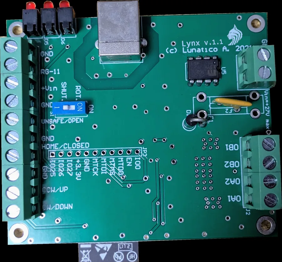
| Motor driver | Bipolar stepper, driven from the board—coils A and B on screw terminals, up to 2.7 A/phase |
| Supply | Up to 27 V DC |
| Speed | Min, max and acceleration fully configurable |
| Motor power | Moving and standstill current set separately, 0–100% |
| Temperature | Compensation from an external DS18B sensor |
| Limits | Home and end sensor inputs, polarity programmable |
| PWM outputs | 3 programmable output, 0–100% |
| Communication | USB; TTL serial for an RS-422 or RS-485 adapter |
| Form | Open board—no enclosure (OEM) |
Backlash and hysteresis are corrected in the controller, in steps, and temperature compensation runs there too: focus follows the temperature without your software being involved.
Datasheets, the Modbus register map, quantities, or a description of something that does not exist yet: the same address for all of it. Somebody who has built the hardware answers.
Offices in Spain and New Zealand. Write in either language; somebody reads it the same day.