
The Caterpillar Dome FC is the "full" model, with separate boards to control the rotation and the shutter. For a standard dome, the system is comprised of two elements:
- The rotation element is made up of the Caterpillar board, connected to a motor (any of 3-phase, DC, or stepper), a rotary encoder, and a home switch.
- The shutter element depends on whether it has one or two parts.
- The opening always has a motor—any type, wired and configured just like the rotation motor—plus two limit switches, with an optional (recommended) encoder.
- If the shutter also has flaps, they are driven by a DC motor through the shutter board's dedicated flap connector, always with two more limit switches and no encoder option. See Shutter hardware for details.
Both boards communicate via an internal Wi-Fi link. The power input accepts from 12 up to 51 V DC; the board provides a regulated +5 V output for powering sensors. If the shutter board is installed in the rotating section of the dome, provisions must be made for it to be powered independently—a battery (charging at the park position) or conductor rails (busbar system) are two common options.
What you'll need
There are sections for each element below further ahead in the document. For now, this table gives an overview of the main elements required depending on your setup.
| Element | Notes | Amount required |
|---|---|---|
| Rotation board | Required for controlling the dome rotation | 1 per installation |
| Shutter board | Optional—for automated shutter and/or flap control | 1 per installation if controlling shutter/flaps |
| Rotation motor | Any type—DC, stepper (with external driver), 3-phase (via VFD, e.g. CFW300), or relay/contactor | 1 for rotation 1 for shutter 1 for flaps |
| Home sensor | Required for rotation—establishes azimuth reference (mechanical or hall-effect). Not used on the shutter, which relies on limit switches instead. | 1 per installation (for rotation) |
| Encoder | Required for rotation—rotary encoder for position feedback. Optional on the shutter's opening (recommended); flaps never take an encoder. | 1 for rotation 1 recommended for shutter |
| Power supply | +12 to +51 V DC | 1 or 2 per installation (1 can be shared by 2 boards) |
| Limit switches | Required if using shutter board—2 per element (open/close), 4 total with flaps | 2 for shutter 2 for flaps |
The following table refers to other elements dependent on the setup. They also have their own sections further into the document.
| Element | Notes |
|---|---|
| External driver for stepper motor / DC motor | The Caterpillar board doesn't drive stepper or DC motors directly, so a driver is required |
| Variable-frequency drive (VFD) | The Caterpillar uses a VFD to control 3-phase motors, paired with the relay expansion board (below) |
| Relay expansion board | A relay expansion board can be used to automate control of motors or drives that are normally operated through simple on/off switches or contactors |
Find 3D printing designs, including board holders, here: 3D files repository.
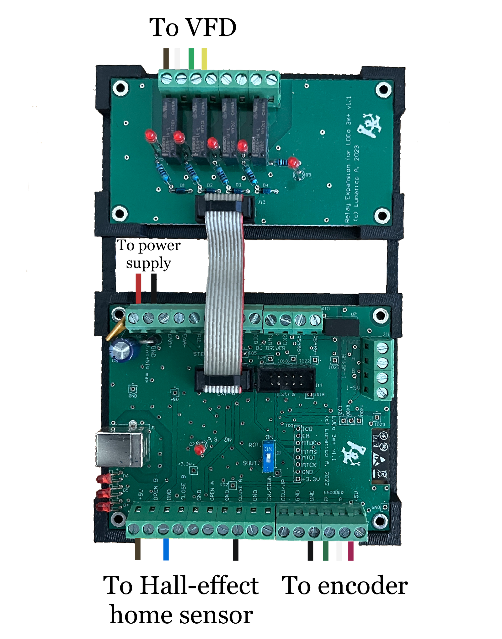
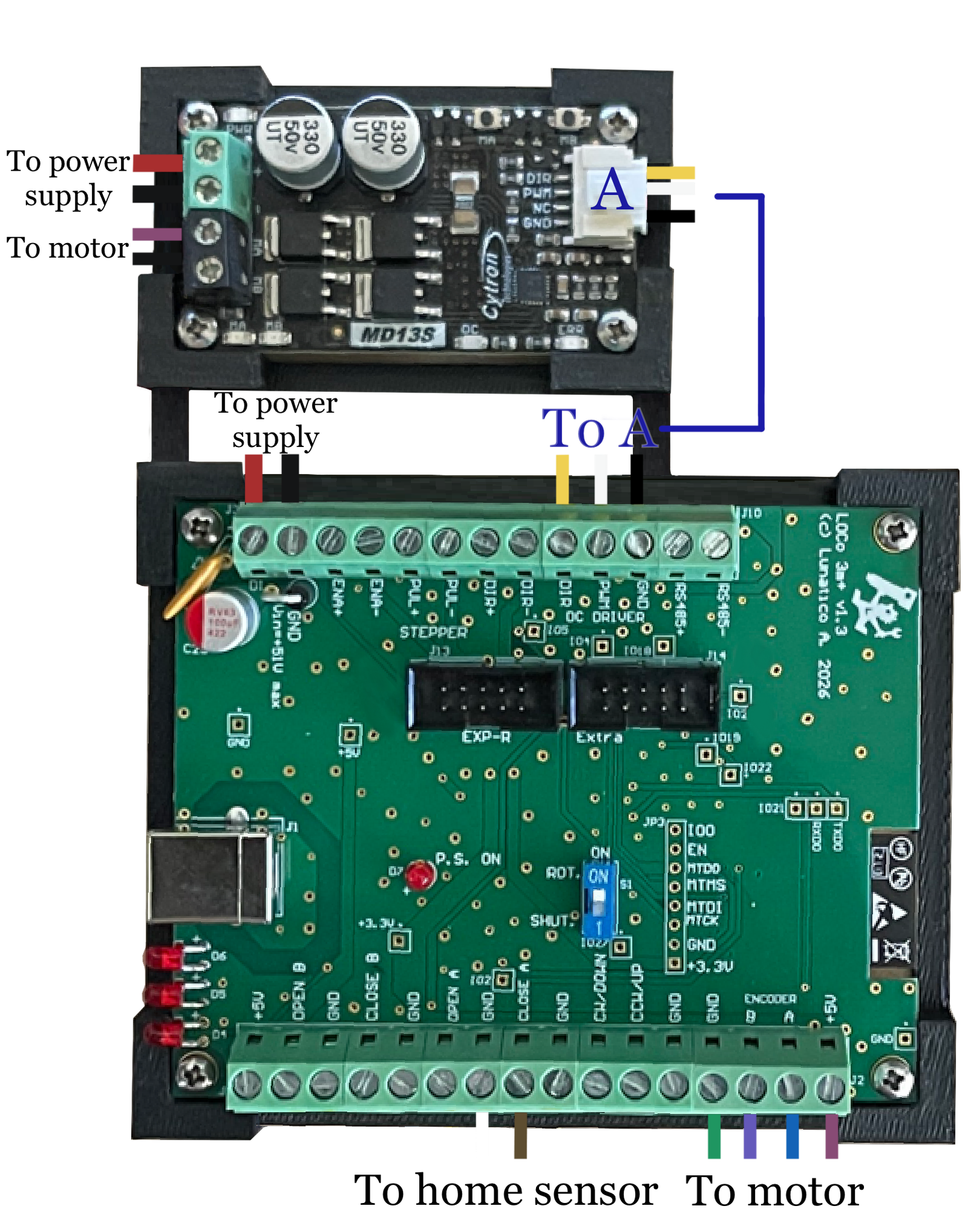
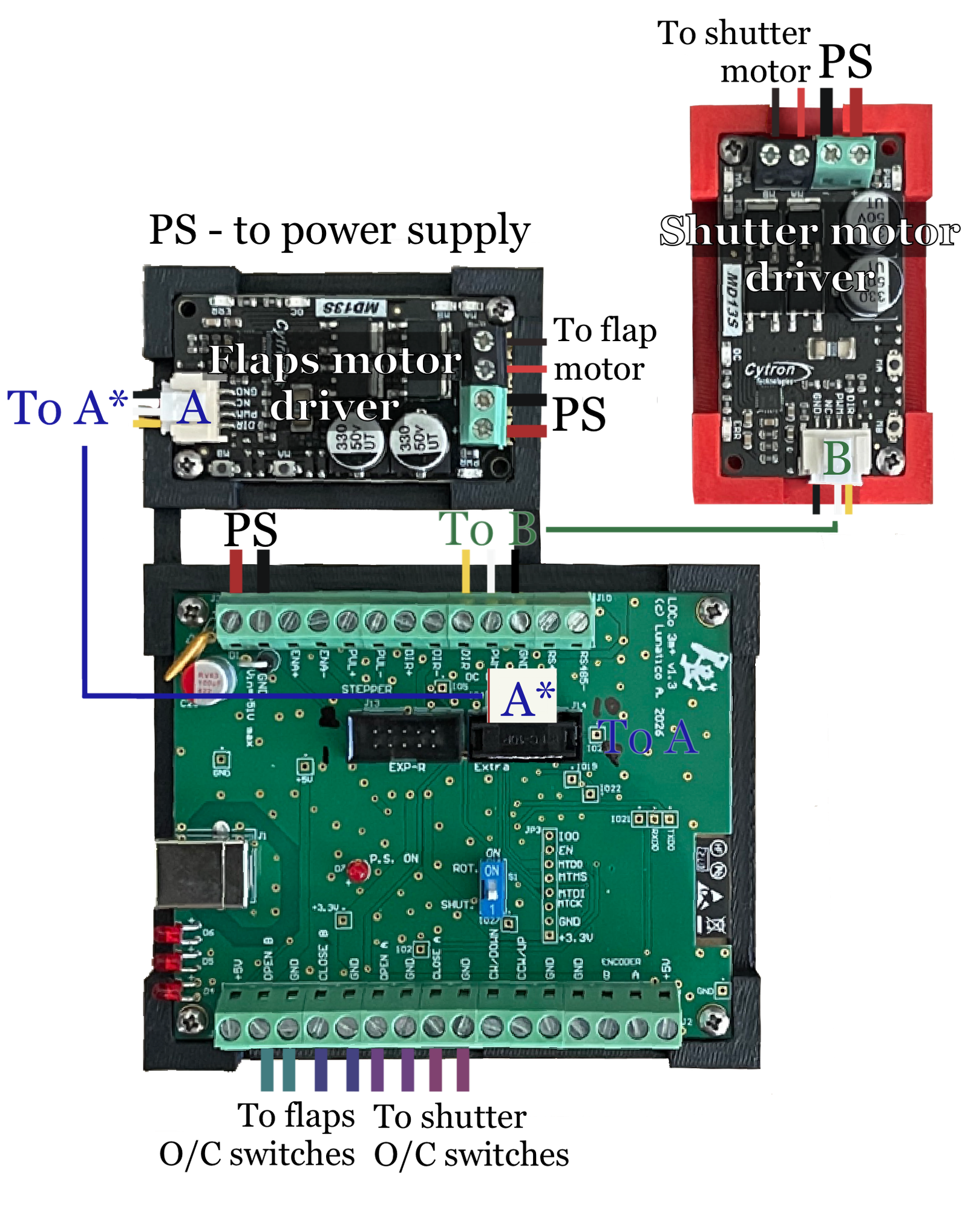
Example board connections
Need: the rest of the pics.