PCB overview
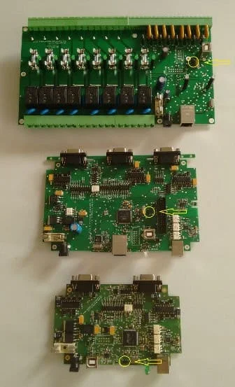
The Seletek PCB carries:
- Motor output terminals — screw terminals for the motor coil wires (A+, A−, B+, B−).
- USB connector — for PC connection and power.
- Handpad connector — for attaching a manual control pad.
- Temperature sensor input — for a DS18B20 or compatible one-wire sensor.
- Relay — for switching accessories such as fans or heaters.
- Erase / bootloader button — used for firmware recovery.
Full assembling and connection guide
The complete instructions — with connector pinouts, wire colour coding, torque specifications for screw terminals, and step-by-step connection procedure — are in the online help manual:
The manual covers the Armadillo, Platypus, and earlier Seletek hardware variants. Use the navigation panel on the left to jump directly to the section relevant to your hardware version and connection type.
Quick start checklist
- Connect the motor cable to the motor output terminals — match coil pairs (do not mix A and B wires).
- Connect the USB cable to the PC. Install the FTDI driver if not already installed — Windows will detect a new COM port.
- Optionally connect a temperature sensor and/or handpad.
- Launch the Seletek software and select the COM port. Test a short focus move to confirm the motor runs in the correct direction.
Developer guide: If you are building custom software or integrating the Seletek into a non-standard setup, the Seletek Developer's Guide (PDF) covers the full communication protocol.