
1.Introduction
Welcome! If you’re reading this, you probably have recently acquired a Caterpillar and are looking to get a speedy start to have your setup up and running as quickly as possible.
These guides will help you with that, but please remember that they don’t contain all the information or if anything is confusing or unfamiliar, you’d be better off checking your device’s manual than trying to fill in the gaps with them. You can find them at the links below:
Model | Usage | Quickstart guide | Manual |
|---|---|---|---|
CaterpillarFC (Full Controller) | For full domes with separate boards for rotation and shutter | ||
CaterpillarSSR | For Roll-Off-Roofs with stepper motors | Guide* | |
CaterpillarR (Relays) | For existing observatories originally operated with manual buttons | Guide* |
If you can’t find it in the manuals, please check our forum or reach out to us—we’re here to help!
*QuickStart guide not available yet. Please use the manual, and if you have questions, get in touch!
2.CaterpillarFC (Full Controller)
1. Get all the necessary elements
This table will help you identify what you need depending on your specific setup:
Element | Notes | Amount required |
|---|---|---|
Rotation board | Required for controlling the dome rotation | 1 per installation |
Shutter board | Optional—for automated shutter and/or flap control | 1 per installation if controlling shutter/flaps |
Rotation motor | Any type—DC, stepper (with external driver), 3-phase (via VFD, e.g. CFW300), or relay/contactor | 1 for rotation |
Shutter motor | Any type as above for shutter. Optional flaps, DC motor only. | 1 for shutter 1 for flaps (opt) |
Home sensor | Required for rotation—establishes azimuth reference (mechanical or hall-effect). | 1 per installation (for rotation) |
Encoder | Required for rotation—rotary encoder for position feedback. Optional on the shutter's opening (recommended); flaps never take an encoder. | 1 for rotation 1 recommended for shutter |
Power supply | +12 to +51 V DC | 2 per installation (or 1 if using conductor bars) |
Limit switches | Required if using shutter board—2 per element (open/close), 4 total with flaps | 2 for shutter 2 for flaps |
Additionally, depending on the motors or drives, you may need one or more of these:
Element | Notes |
|---|---|
External driver for stepper motor | The Caterpillar board doesn’t drive stepper or DC motors directly, so a driver is required |
External driver for DC motor | |
Variable-frequency drive (VFD) | The Caterpillar uses a VFD to control 3-phase motors, paired with the relay expansion board (below) |
Relay expansion board | A relay expansion board can be used to automate control of motors or drives that are normally operated through simple on/off switches or contactors - including VFD driven ones. |
By the way, remember you can find 3D printing designs, including board holders, here: 3D files repository.
Step 1 checklist
Feel free to print this page and tick the ones you’ve got already.
Element | Amount required | Check |
|---|---|---|
Rotation board | 1 per installation | |
Shutter board | 1 per installation if controlling shutter/flaps | |
Rotation motor | 1 for rotation | |
Shutter motor | 1 for shutter | |
1 for flaps | ||
Home sensor | 1 per installation (for rotation) | |
Encoder | 1 for rotation | |
1 recommended for shutter | ||
Power supply | 1 or 2 per installation (1 can be shared by 2 boards) | |
Limit switches | 2 for shutter | |
2 for flaps | ||
External driver for stepper motor | 1 per stepper motor | |
External driver for DC motor | 1 per DC motor | |
Variable-frequency drive (VFD) | 1 per 3-phase motor | |
Relay expansion board | 1 per 3-phase motor or depending on setup |
2. Connect all the elements
We’ll quickly go over how to connect all the elements, for detailed instructions, hardware examples, etc. please check the relevant section of the manual.
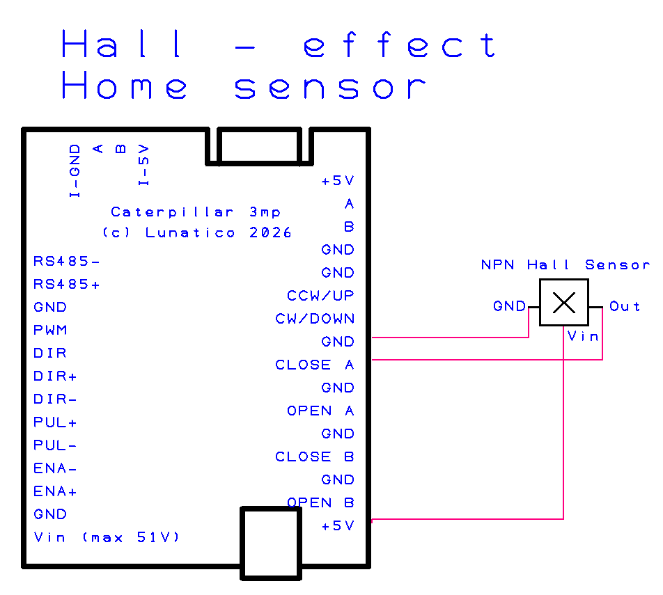
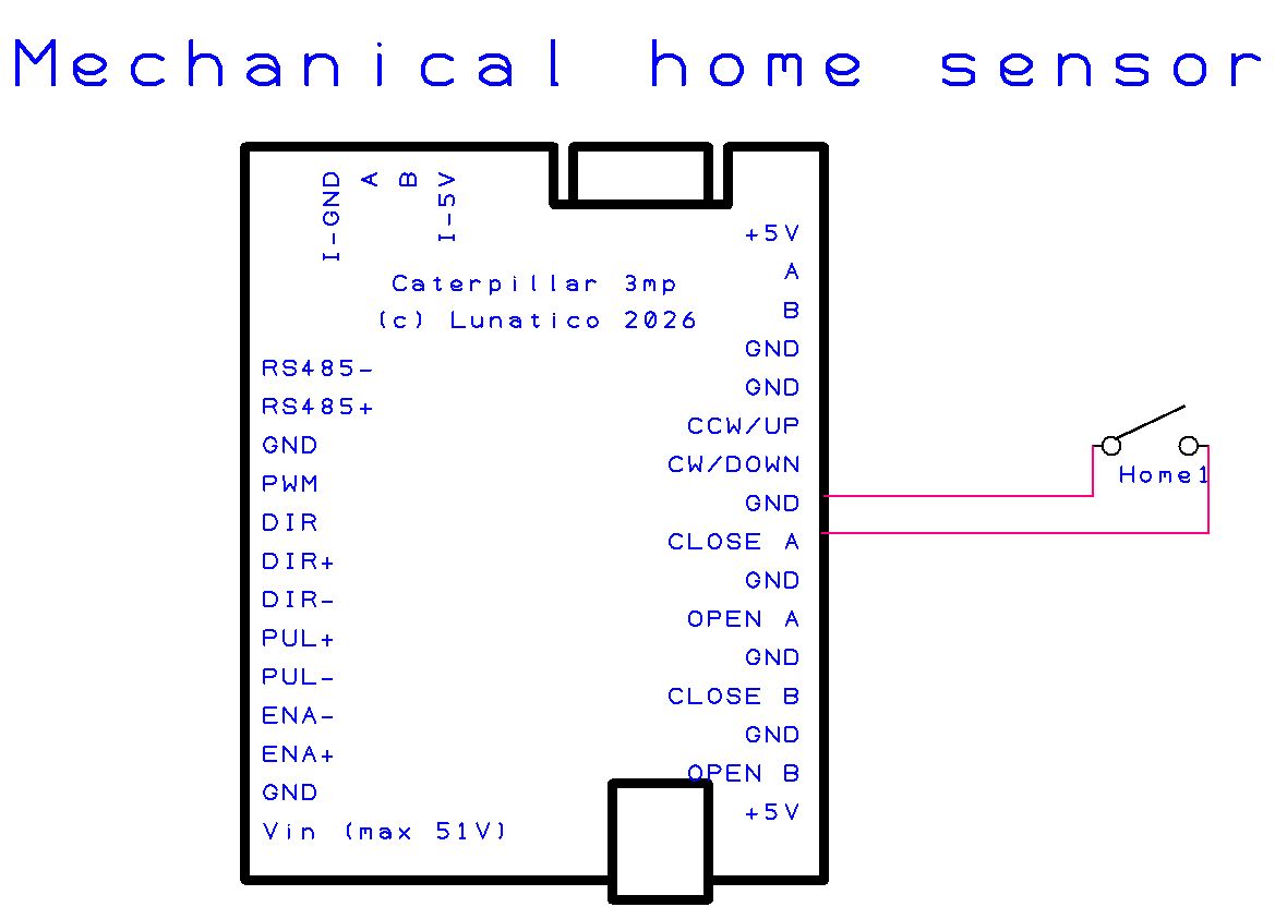
- Wire up the home sensor. We recommend a hall-effect one, wired like this:
But you can also use a mechanical one, wired like this:
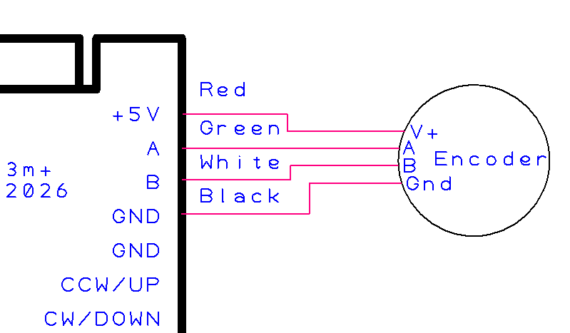
- If not using a stepper motor. Wire up the encoder (unless using a stepper motor). For the shutter, this is optional, but recommended!
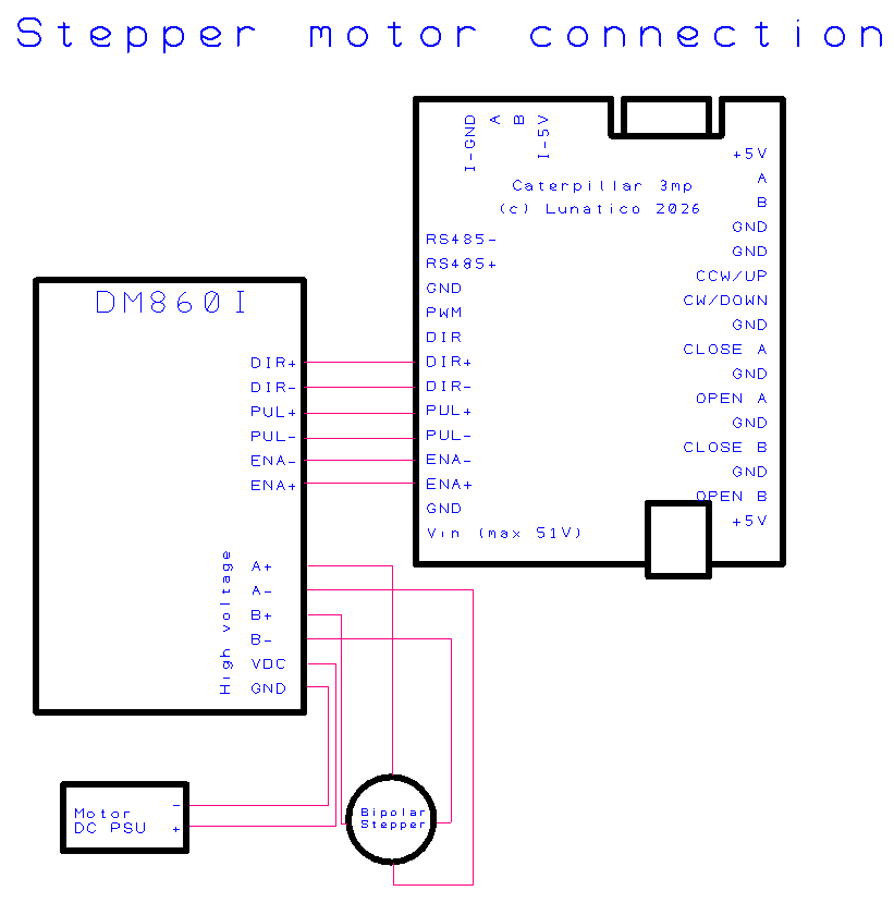
- If using a stepper motor. Set up the external driver.
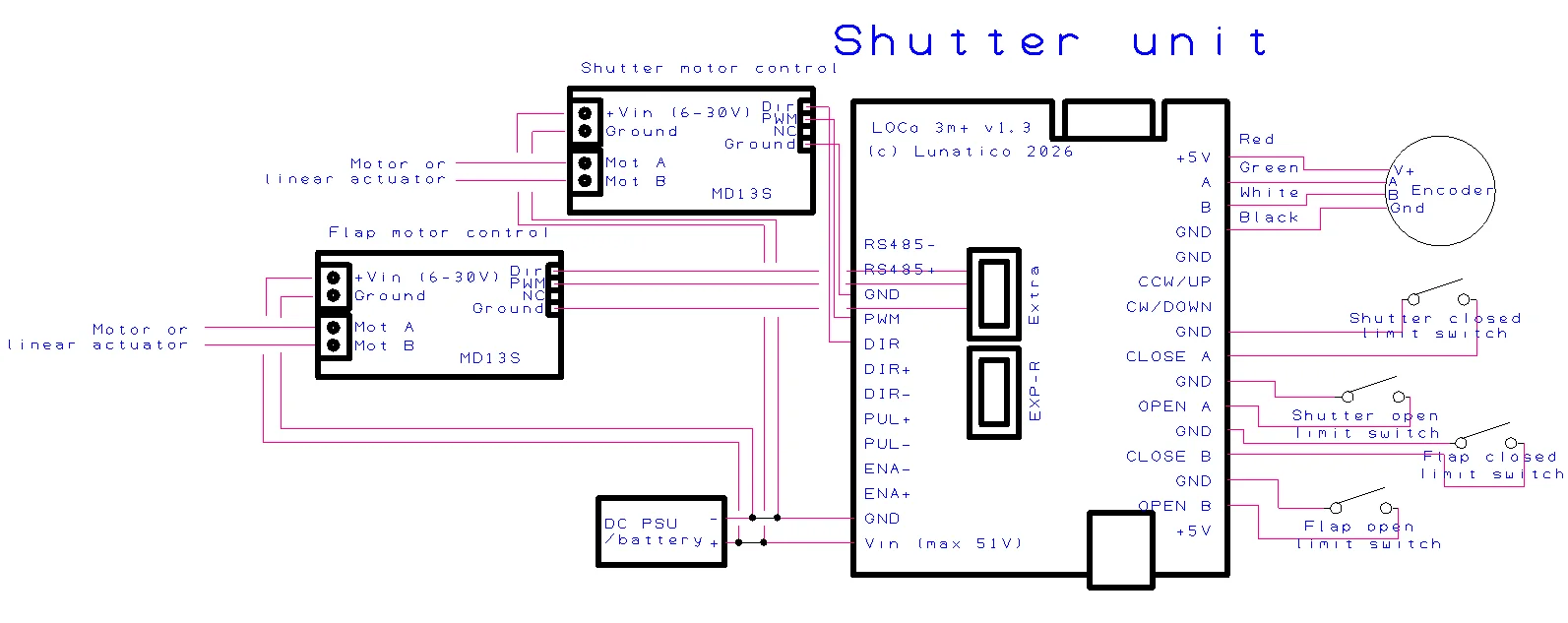
- If using a DC motor. Set up the external driver. The diagram below shows connections for a Cytron MD13S.
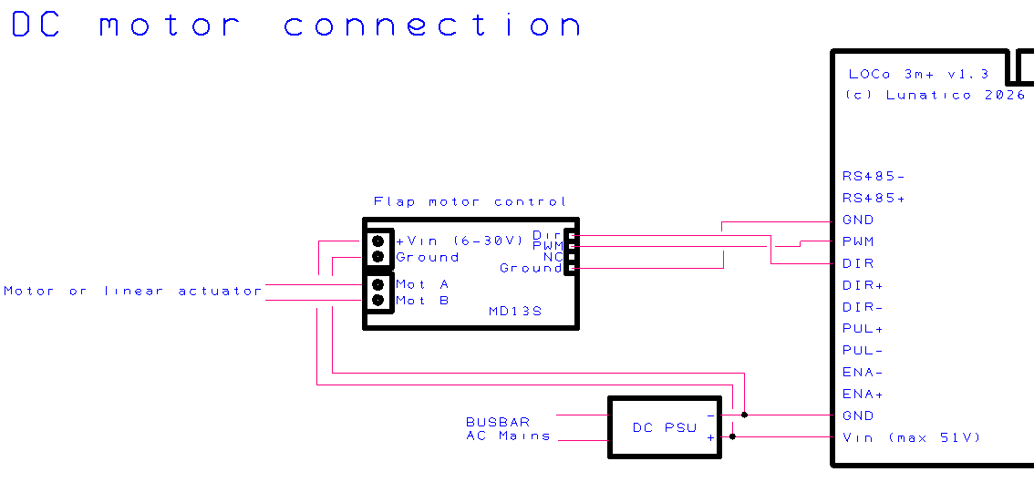
See also a complete shutter unit below: opening (DC) + flaps + encoder + limit switches + PSU.
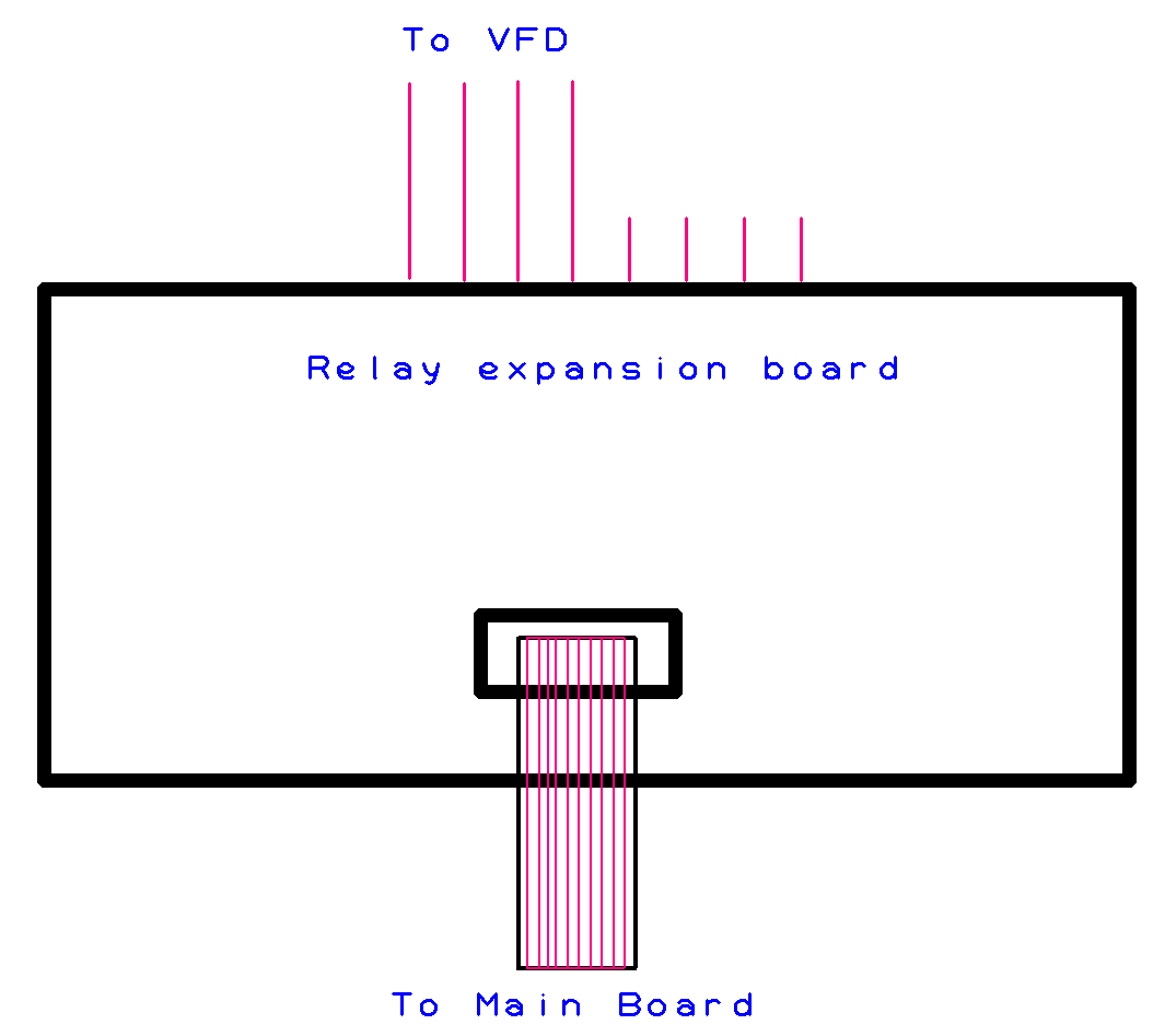
- If using a 3-phase motor. Set up the Variable-frequency drive (VFD) and relay expansion board.
To connect to the relay expansion board, use the flat cable provided.
D
4. Perform the initial setup with the "Initial motor configuration and setup" tool, as indicated below
These steps are to be carried out by the observatory manufacturer. If somebody else did that for you, feel free to skip ahead.
The Caterpillar can be controlled from any operating system, but the first first configuration has to be done with the Initial motor configuration and settings application, which runs on Windows (you’ll probably only use this once).
- Download the Caterpillar’s USB Windows drivers.
- Download the The Caterpillar's software package. It includes Initial motor configuration and settings and the ASCOM dome driver and ASCOM safety monitor driver – if using INDI, don’t panic! We’re not looking at the drivers in this section.
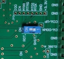
- Connect the Rotation Caterpillar board to the Windows computer via USB (check the blue switch to find out if a board is configured as rotation or shutter). If using a shutter board, then power up both boards, so they’ll connect to each other.
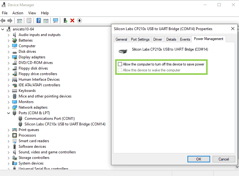
- Open Windows Device Manager to find the COM port assigned to your Caterpillar (it’ll show up as a CP210x USB to UART Bridge), and disable “Allow the computer to turn off this device to save power”.
- Open Initial motor configuration and settings and select the appropriate port from the Serial Port dropdown.
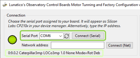
The line marked in light green in the image above will get populated once the connection is successful.
- If you wish to, configure the WiFi now. It should be straightforward, otherwise please head to the manual. If you do, you can also connect from Inital Settings and Configuration via WiFi instead of with the USB.
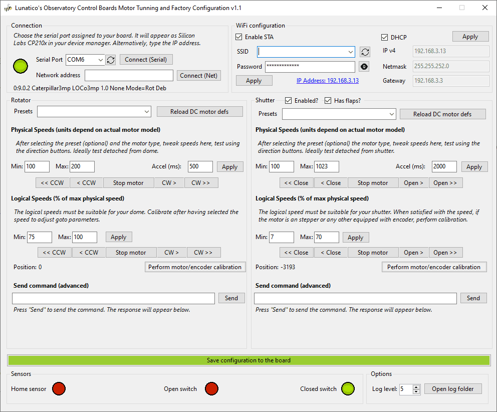
- If your dome has a shutter controlled by a separate Caterpillar board, tick the “Enabled” box, and, if applicable, the “Has flaps?”.
Click Save configuration to the board. On power on, the boards will connect to one another over a private, internal Wi-Fi link (you don’t need to do anything).
When using a shutter, note that the rotation board controls the shutter board; you do not need to address the shutter board separately from ASCOM. Similarly, the rotation board will automatically update the firmware of the shutter one when required. From the user point of view, it is as if only the rotation board existed.
- Select your motor preset(s). This’ll reset all parameters to the factory defaults for the selected motor type. This shouldn’t be a problem since this is the first time you’re touching the settings, but worth keeping in mind. The board will reboot automatically, and Initial motor configuration and settings will reconnect after a few seconds.
Wondering which preset is right for you? Check this table:
Preset
Motor/drive type
Encoder
Stepper
Stepper motor via external driver
Not needed—position comes from steps
DC motor with encoder
DC motor via external driver (e.g. Cytron MD13S)
Yes
DC motor no encoder
DC motor via external driver
No
Relay motor with encoder
Relay-driven motor or contactor, including a VFD driven through the relay expansion board
Yes
Relay motor no encoder
Relay-driven motor or contactor, including a VFD driven through the relay expansion board
No
Note that The "no encoder" presets are only offered in the Shutter preset dropdown—on the rotator, an encoder is always required except with the Stepper preset.
- Set the physical speeds if necessary (your preset loads sensible defaults, only adjust these if you know your motor's characteristics and are seeing stalling or noise). Physical speeds are the raw parameters the motor driver works with, and once set you won’t need to touch them again, they only need to be configured once per motor/driver combination.
Min
The slowest speed the motor can turn without stalling. Below this, the motor may not move reliably
Max
The fastest safe speed for your drive system
Accel
How quickly the motor ramps up from min to max, in ms. Please note, for the shutter motor, a short acceleration time might be needed depending on how the limit switches are installed, to avoid overshoot.
Test using the jog buttons, with the motor disconnected from the dome or shutter mechanism.
- Only once you’re happy with your physical speeds, move on to logical speeds*. These are the speeds your ASCOM driver and automation software see, and they are percentages of the physical range. Tune these numbers to match your specific installation.
Unlike the physical range, you will need to revisit this setting whenever the dome’s mechanics change.
*If your motor type is relays (CaterpillarR), speed controls aren’t available so the fields will be disabled.
- Click Apply in each speed section to send the values to the board, then Save configuration to the board to persist them.
- Check the motor directions by using the jog buttons of the rotator and, if applicable, the shutter. Note that they won’t stop at the limits by themselves, so be ready to press Stop motor if necessary.
Look at whether or not they're moving in the direction the jog buttons indicate, if not, you'll need to swap the motor wirings.

Note that encoder wiring won’t need to be swapped, if it’s reading the wrong direction it’ll correct itself.
- Run the motor and encoder calibration (when using an encoder). This’ll match the encoder response to the motor motion. Make sure the dome is clear to move through its full range of travel, and then click Perform motor/encoder calibration.
The dome will exercise the motor in both directions, moving and stopping repeatedly. Do not interrupt this process unless necessary.
On success, a confirmation dialog appears. Click Save configuration to the board immediately to preserve the calibration data.
- Ensure you’ve pressed Save configuration to the board, and then exit the application.
5. Use your ASCOM or INDILib driver to calibrate the rotation (full calibration), and optionally the shutter.
If using ASCOM keep reading, if using INDI press here.
Calibration with ASCOM
The Caterpillar’s software package which you downloaded earlier includes the ASCOM dome driver and an ASCOM safety monitor driver for the optional weather input.
- If you don’t have it, install the ASCOM Platform.
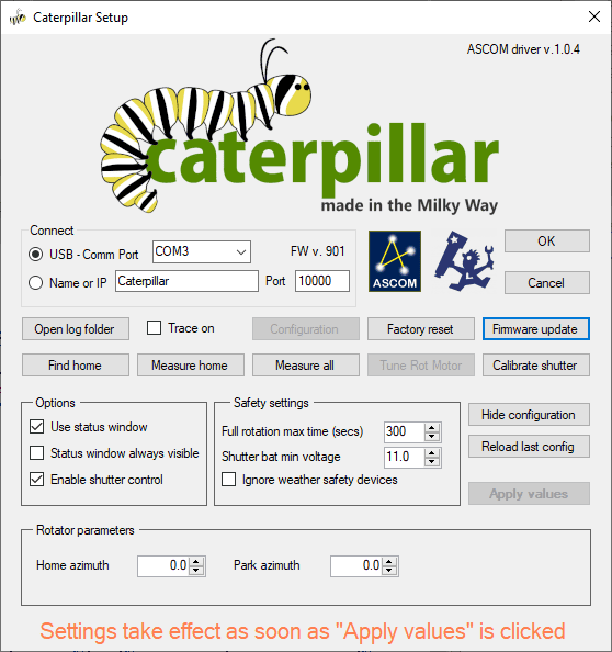
- In your astronomy software’s dome chooser, select Caterpillar Dome from the list. Open the driver’s Setup dialogue.
- Connect to your Caterpillar by selecting the COM port (if connecting via USB), or the IP address (if via WiFi).
- Run Measure all, and if you have a shutter, Calibrate shutter.

- Now’s a good time to take a look at the options and safety settings (toggle them with Configuration), and enable or modify any that you feel like editing. They should all be relatively straightforward—for details, check the manual.
Skip the INDI section by pressing here.
Calibration with INDI
The Caterpillar is fully compatible with the INDI driver for the Beaver, which is called NexDome Beaver. We intend to create a dedicated driver for the Caterpillar, but, for now, please use that one.
- If you don’t have it, install INDI. The driver is included with the default ones.
- When setting up your profile, select NexDome Beaver from the driver list.
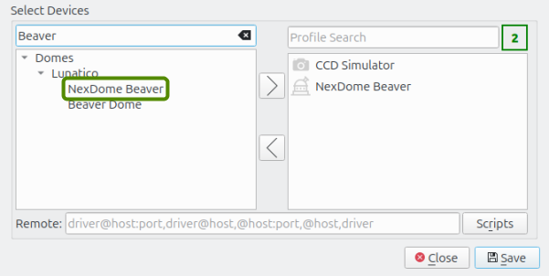
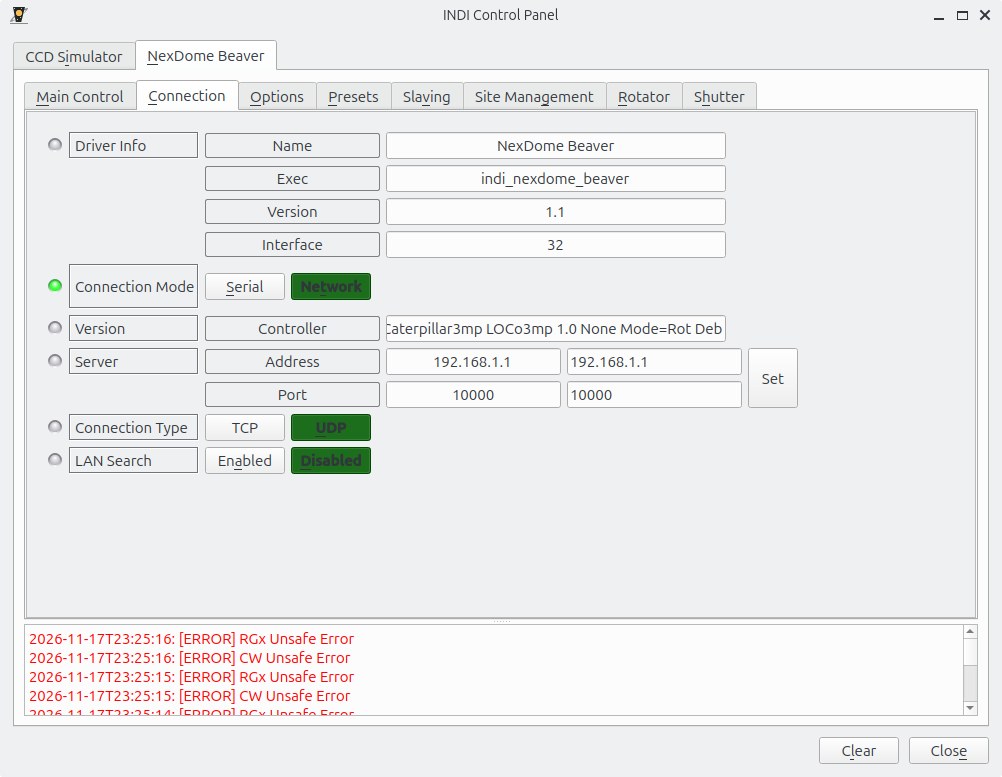
- You’ll be able to connect via Network if you’ve set that up (step 6 of section 4). Otherwise, just use a USB cable and choose Serial as your connection mode instead.
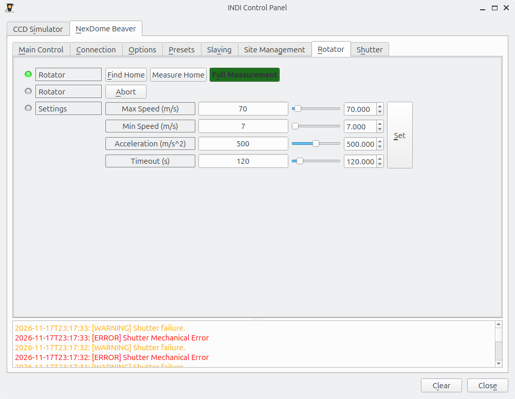
- Head over to the Rotator tab and run Full Measurement.
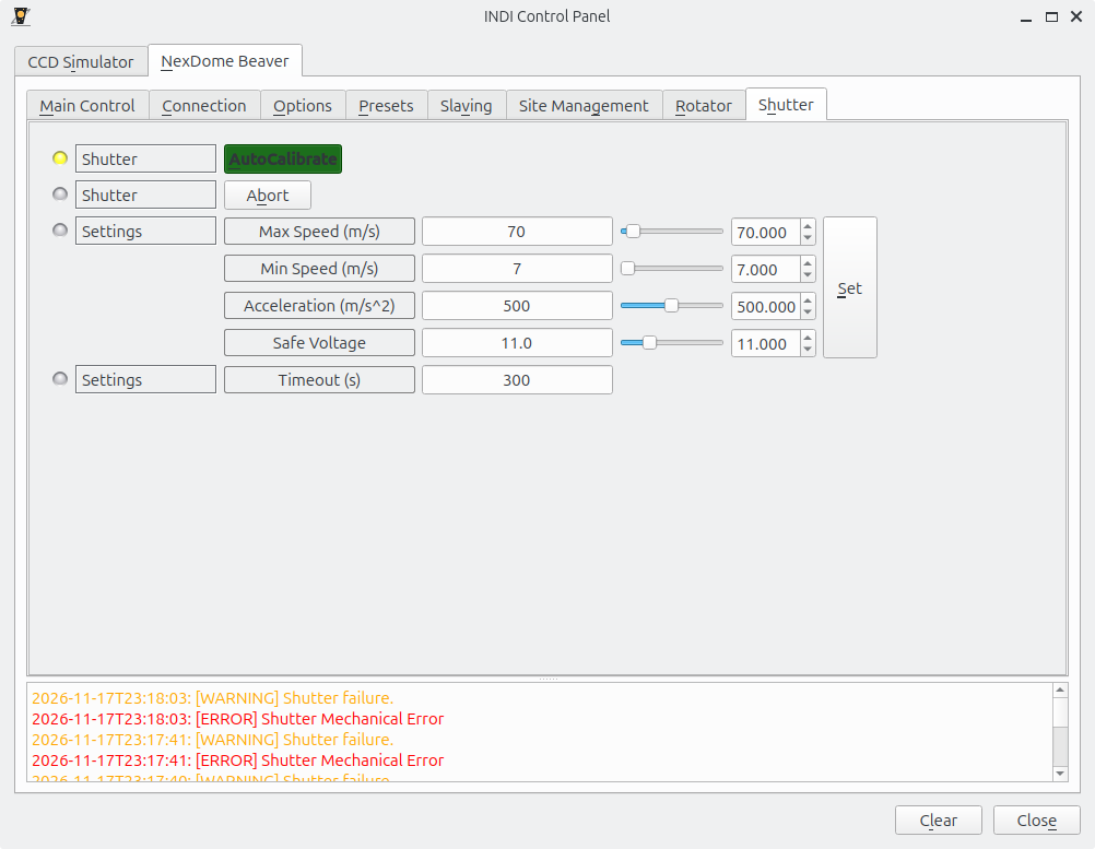
- Then, in the Shutter tab, run AutoCalibrate.
6. Enable slaving to the telescope
Depending on your setup, you’ll do this process from your automation software, the ASCOM Device Hub, or elsewhere. We’ll exemplify it with the ASCOM Device Hub in this guide.
- Open ASCOM Device Hub.
- Go to Tools → Setup → Dome Setup.
- Open Dome Setup → Geometry and enter:
Dome Radius
The inside radius of the dome
GEM Axis Offset
Distance from the GEM pier to the dome's geometric centre
E/W Offset
East–West offset of the mount's intersection point from dome centre
N/S Offset
North–South offset
Up/Down Offset
Vertical offset
The N/S, E/W, and Up/Down parameters describe by how much the mount's optical axis intersection point is offset from the centre of rotation of the dome. The best way to measure these is often by taking differences—position the telescope at different azimuths, note the dome positions required, and back-calculate the offsets.
- Once those values are set, click Choose and select the Caterpillar ASCOM driver.
- Click Connect.
- Configure the Telescope tab to connect to your mount's ASCOM driver, then enable slaving. Recommended parameters:
Slave precision
2°
Slave frequency
Every 5 seconds
Driver polling
Every 2 seconds
- After setting that, save and back in the dome tab, press Connect Dome.
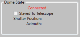
- Check the Slaved To Telescope box.
7. Optional: set up the ASCOM Safety Monitor
Included in the Caterpillar installer, you will have downloaded the safety monitor driver. If you set it up, you will be able have your Caterpillar close the dome automatically when conditions become unsafe. You can use the driver with the CloudWatcher or some other weather monitor, such as Hydreon’s rain gauges.
We won’t go over how to set it up in this guide, the process is similar to setting up the ASCOM dome driver.
8. Know where to find help
If anything doesn’t work, if you need to troubleshoot your dome, if you’re confused about anything… we have the following resources available:
- Of course, you have the Caterpillar Full Controller Online Manual at your disposal. Notice in particular section 4—troubleshooting.
- The Caterpillar Area of our forum is also of interest. The forum is great for speaking to other Caterpillar users, and we also strive to respond to all the threads we can help with. Posting there also helps others find the solution to similar issues.
- You can always get in touch with us at support@lunaticoastro.com. We’re happy to help!