
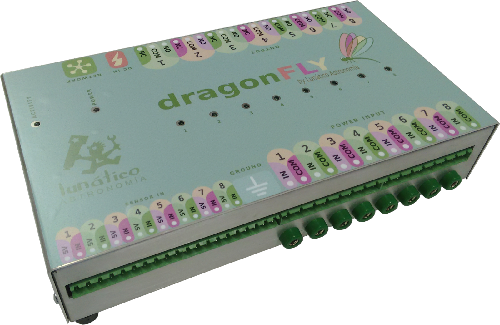
Introduction and Windows software
1. Introduction
Setting up the remote control system of your observatory requires quite a bit of effort – our Dragonfly has been designed to help make it easier.
The Dragonfly is a very powerful and versatile device. Every effort has been made to make it simple to use, yet allowing for full customization. Setting it up to remotely control our observatory can be accomplished with little effort, yet you can go as deep as you want and have it performing incredibly complex tasks if needed.
The Dragonfly operates at different levels:
- it controls several relays and can read several inputs. These are at the heart of everything, and they can be accessed from:
- a simple web interface,
- a custom smartphone app (from anywhere),
- Windows, linux or OSX software,
- custom scripts,
- web javascript,
- RESTful API,
- …
- it is intelligent, and can perform advanced functions by itself (we call these “macros”, and they are explained in depth in the Dragonfly macros manual), such as:
- registering in our cloud server for Zero Configuration connections,
- checking internet status, and, for example, resetting the router if failed,
- sending us an email (or push message) if the roof is open and the weather unsafe,
- parking network-enabled mounts,
- …
- it includes a 3 level (read, relay change, configuration) password-based security system
- with the PC software, the possibilities are multiplied1:
- scripts can be launched when any relay or sensor changes,
- the position of the mount can be checked, commanded to park,
- the roof can be commanded from 3rd party programs (via ASCOM or INDI/INDIGO),
- the opening and closing procedures can be customized without limit: you can park the mount, lower the pier, send an email… anything;
- …
1 Not all features available on all operating systems, but more are constantly being added.
2. Some basic background on relays
So, firstly, a bit of background – feel free to skip to section 3 if you're confident in your knowledge about relays and the like.
A relay is a very useful device indeed – being an electrically operated switch, it enables appliances such as our Dragonfly to turn on and off other appliances.
Let's compare relays and push buttons:
- Every relay has two sides: the control side (your finger able to push or release the button) and the proper switch (the internals of the push button opening or closing the circuit).
- The most common push buttons leave the circuit open if nobody is pushing them, and close the circuit when pushed (push buttons working the other way around also exist). These most common push buttons are called “normally open”: they are open until some effort is made to change the state. The other model, yes, is called “normally closed”.
- The same applies to simple relays: they can be “normally open” or “normally closed”. When a relay is unpowered, it is in its normal state. When it is powered (power is applied to the control side, that is, like a finger push), the state changes. If we name the contacts of the relay IN and OUT, when the relay is closed, current will flow between IN and OUT, because internally IN and OUT will be connected. Conversely, if it's open, no current will flow.
So, a normally open relay won't allow current flow unless powered, and a normally closed relay will allow current flow unless powered.
So far, so good.
But some relays are a bit more complex (and useful!). They have 3 contacts – let's think of them as IN, NO (for normally open) and NC (for normally closed). The unpowered or relaxed relay will have IN connected to NC – with the ability to change this connection, and short IN with NO when powered (breaking of course the IN to NC connection).
3 contact relay unpowered | 3 contact relay powered |
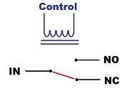
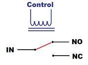
For added flexibility, we use both kinds of relays in the Dragonfly.
3. Planning
As we're going to follow a step by step procedure to set up our observatory, let's start by deciding exactly what we want to be able to control:
- opening / closing the roof
- powering the mount
- powering the CCD Camera(s)
- forcing off the observatory lights
…and monitor:
- the position of the mount (at home or not) if needed to operate the roof
- the position of the roof
- the power (mains availability)
…remotely. The above list can be considered a typical setup. Of course, it is not the same to set up your backyard observatory so it can be controlled from the living room as setting up your truly remote observatory 300 Km away from home.
Note: all the following examples will be aimed at setting up an observatory with these requirements; please use the same relay / sensor positions, as this will greatly simplify the process.
4. Electrical setup
The setup of the Dragonfly is quite straightforward – it may involve, however, dealing with dangerous voltages and currents (depending on your setup); please contact a qualified electrician if you don't have the skills needed to perform a 100% safe setup.
Note: when naming the state of any relay, we'll think of the “NO” output. This applies to the software, too. So, we'll say the relay is OPEN if its NO output is. All relays will be open when unpowered. Conversely, we'll say the relay is CLOSED if its NO output is connected to the input side.
If you take a look at the sticker covering the upper side of your Dragonfly:
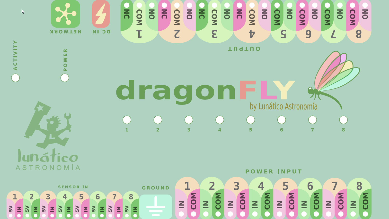
…you'll notice we've used this naming convention for labelling the input and output connectors.
And another thing to notice: Power Input connectors are on the lower side, Power Output ones on the upper side. Current, be it AC mains (max 240V) or DC from a battery or power supply, will enter the Dragonfly via the Power Input and will be blocked or routed to the Output side. On the Output side we'll have our devices, mount, roof, CCD Camera or whatever.
So, to make sure how the internal wiring goes is clear:
- “COM” will be internally routed from the input to the output side – always
- “NO” (Normally Open) will be connected to “In” when the relay is closed by the software
- “NC” (Normally Closed, only available in relays 1 to 4), will be connected to “In” when the relay is open in the software
When the Dragonfly is unpowered, all the relays will be in the relaxed (normal) state, so:
- All “NC” contacts, present in relays 1 to 4, will be connected to their matching “In” (so they'll be closed)
- All “NO” contacts, will be, of course, just open
Graphically:
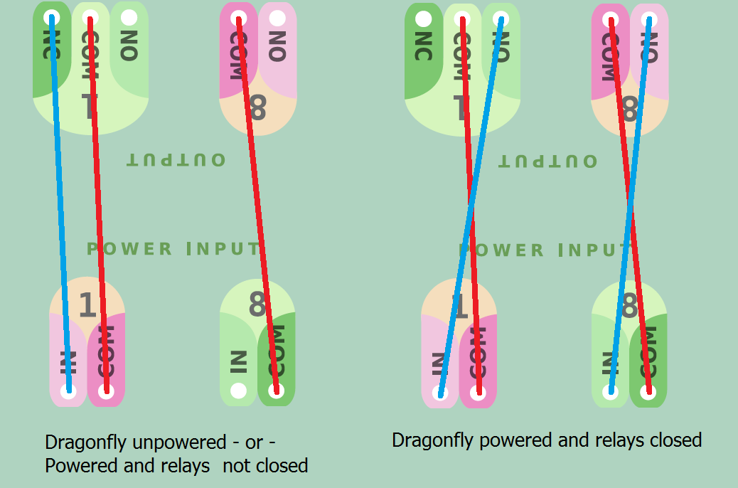
So what are the “NC” contacts for? When designing the Dragonfly, we noticed that certain things should be powered at all times except during the imaging session. One simple example is the observatory lights – you may choose to route the hand switch through the Dragonfly in such a way that no one can accidentally turn on the lights when you are imaging. You can even use the “NO” contact of the same relay to power on some other thing when the lights go off.
In my case, I have an electrical dehumidifier and I want it off for sure before the roof is opened!
So let's set up things for our minimalist observatory – adding the dehumidifier:
Relay 1 → Roof control (pulsed – that is, a push button, as standard in many garage door automation motors)
Relay 2 → Mount
Relay 3 → CCD Camera
Relay 4 → Observatory lights
Bear in mind! – at the input side, for each relay:
- neutral (AC) or ground (DC) should be wired to “COM” (common)
- phase or live (AC) or positive (DC) should be wired to “In”
So, the wiring, input side:
- the same for relays 2, 3, and 4: mains neutral to COM, mains phase to IN
- for relay 1, roof, as we want to “push a push button”, we'll wire COM and IN together (just a short wire connecting them both). This case is different as we do not need to power the roof motor, but just to push a button, something like this:
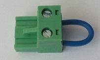
…and output side:
- Relay 1: COM and NO to the roof motor push button
- Relay 2: COM and NO to the mount power supply
- Relay 3: COM and NO to the CCD Camera power supply
- Relay 4: COM and NC to the observatory lights. NOTE in this case it is NC, not NO, as we want the lights working in normal conditions
Note: the box of the unit must be connected to ground (earth).
The LED for each relay will be on when the relay is closed.
We can't forget to mention earthing; the Dragonfly incorporates 8 banana-style plugs at each side to make earthing really simple. They are all connected together and to the metallic box.
The rule is simple; all A.C. current appliances should be earthed. Also, even if all current routed by the Dragonfly is D.C., the box should be earthed; this is accomplished by wiring any of the 16 plugs to earth.
Regarding the sensors, they are connected to the “sensor in” section; most of them (proximity, contact, etc) will just need the “+5v” and “In” connections. For other, more complex sensors (such as our Sharp distance one), ground is also needed; there are 4 ground plugs between the “sensor in” and “power in” strips.
There's a separate instruction sheet on wiring things to the Dragonfly, should you need it, please refer to our website.
5. Windows software
Important note: if not using Windows; for Linux and OSX, there are 2 implementations of the drivers, INDIGO and INDILib. Please check their respective websites for more information.
Let's look at the supplied software step by step.
We strongly suggest first making sure everything in the observatory works as intended and can be operated safely from remote, but with you supervising and actively switching things on, off, and looking at the sensors. Only once you are comfortable with this, should automation be addressed.
5-a) Installation
Installing the software is as easy as it gets. The only prerequisite is to have the ASCOM platform installed. You can download it freely from:
Once ready, download the Dragonfly software from our webpage :
…, run the installer and follow the simple instructions.
5-b) Connecting
If, after installing, you launch the software (Dragonfly, from the start menu or apps), it will automatically try to connect to a dragonfly with the default name (not surprisingly, “dragonfly”)
The top of the window will look like this one:
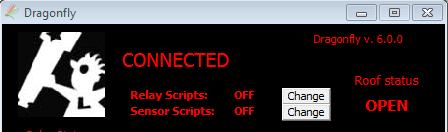
In case you have any problem connecting to your controller, check section 7.
5-c) Remote control
The remote control software supplied with your Dragonfly allows you to name every physical connection so you don't have to guess, apply restrictions, configure relays and sensors… It is really easy to understand and we'll review it while working on our example observatory.
So we are going to spend some time with the Dragonfly control panel, as seen in the following image, which will also be visible.
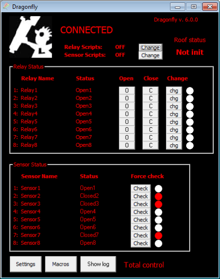
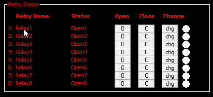
We'll focus, for now, on the two big areas, the upper one for relays, the lower one for sensors. It's easy to see there are 8 rows of relays and 8 of sensors, just as in the physical box.
Let's give a name to each relay, and even to each state – so relay 1 becomes “Roof motor”, relay 2 “Mount power”, with closed becoming “On” and opened “Off”, etc.
Just click over the current name of the relay (where the mouse cursor is in the following image).
… and you'll be presented with the settings for that relay:
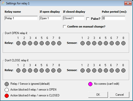
This has two zones: the upper one, and an advanced area to define restrictions. Let's start with the upper one.
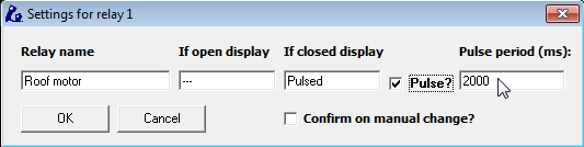
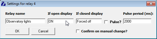
You can name the relay and what should appear when it's closed and open. You can also define it to be a “pulsed” relay, as appropriate in the roof motor configuration. The pulse period, you surely guessed it, is the approximate duration of the pulse in milliseconds.
Keep naming relays (and ignoring the restrictions for the moment):
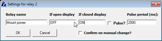
… please continue to do the same for the CCD power and observatory lights – don't forget the lights will be off if the relay is closed!
Last, and to avoid accidental clicks, get back to the roof motor relay settings; you can protect any relay selecting…
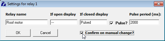
… the “confirm on manual change” option. This way, you'll be asked for confirmation if you click any of the buttons concerning that relay.
Now the relay panel should look like this:
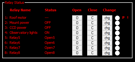
Notice both the “P” and the “!” on the right side, roof relay; the “P” means it is pulsed, the “!” means you'll be asked for confirmation before any action takes place.
The same naming system applies to sensors:
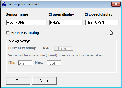
For the roof (roll off roof) we suggest using two switches, one for signalling “open” and another one to signal “closed”, this way we will notice should the roof stop mid-way.
So before an imaging session, with our observatory roof closed, our window will look like in the following image.
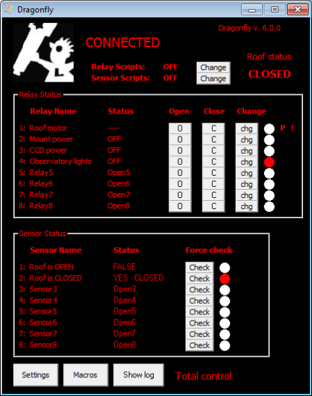
Lights enabled, Roof not opened – but closed, ccd and mount off. We are deliberately leaving the telescope park sensor for the moment. Great.
Switch off the lights (click “Close” in their row) and click “change” (chg) in the Roof motor row (NOTE: the pulse we defined earlier will only work when change is clicked).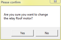
As we also selected the “Confirm on manual change”, we'll get a confirmation window.
… select yes to proceed. You can now also power the mount and CCD Camera.
The roof will open, and, once fully opened, we'll have the following image.
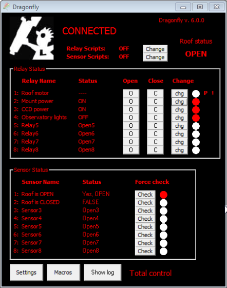
… as you can see, it reflects the current state of things.
Let's review now the things we've ignored for the moment…
Firstly, the roof information zone.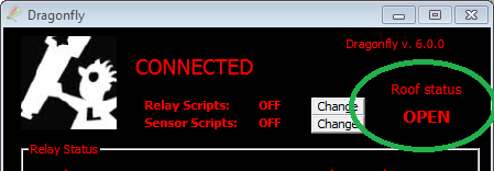
If you plan to use ASCOM automation, then you'll have here the current status of the roof. Clicking on that area, you can command it to open and close conveniently:
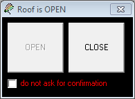
Note: you can disable this functionality by deleting the related roof scripts from the disk.
Here you can see the relay and sensor scripts, disabled for the moment.
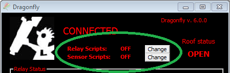
The software can execute a script every time a sensor or relay changes. Check the Automated control – on / off scripts section.
And maybe you've also noticed the “Total control” message:
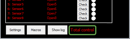
The Dragonfly implements a 3-level access control system, designed to assist in shared environments, or hosted observatories, to add security. For an isolated observatory, this is usually not needed.
Clicking on the “Macros” button will display a new floating window:
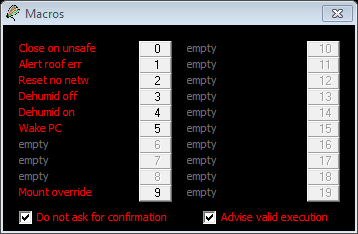
From here you can manually launch (ignoring the conditions) any macros that you have programmed using the “DragonflyConfigurator”. The options are self-explanatory. Note you need at least relay change access in order to execute the macros.
The last thing worth mentioning is the settings.
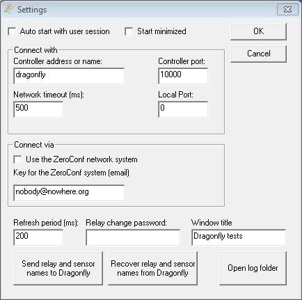
Ignoring, for the moment, the communication related ones (sections starting with “Connect...”, addressed in section 6):
- Auto start with user session: check this option if you want the software to be launched (and connected to the Dragonfly) as soon as your windows session is started
- Start minimized: exactly as it says.
- Refresh period meaning the sensors (and relays) will be checked, one at a time, every 250ms (or any other frequency, between 100 and 60000 ms). —For local area networks, 250ms or even faster is ok. If you will be connecting from far away, via internet, using a higher value (1000ms or so) may be better -you can always force the immediate check of a sensor by clicking on that sensor’s “Check” button.
- Password, as explained earlier
- Window title – useful in case you're managing several dragonflies.
- Send and Recover names to / from the Dragonfly – convenient way of storing all the relay and sensor settings (name, name if open and closed, if analog, or pulsed, etc...) in the Dragonfly – and recover them from the Dragonfly.
- During normal operation, any changes you make are stored locally in your computer, and also inside your Dragonfly. If you install the software in a new computer, recovering the names from the Dragonfly will be useful to be set up in no time. If installing Dragonflies for other users, for example, forcing the sending of everything to the Dragonfly can also be a time saver.
- Open log folder will open a Windows file explorer at the folder where the Dragonfly logs are being stored. These logs contain:
- Data relating to every relay change
- All the information shown in the log window, from scripts or from anywhere
Addenda 1: analog sensors
Some sensors, such our IR distance measuring one, yield analog instead of digital values. This means the reading from the sensor, instead of just open or closed, will be a value between 0 and 1024.
You may want to skip this section if you're not going to use any analog sensors – just know you can use them if the need arises.
In order to use one of these, you'll have to configure it as analog (note that we're using sensor 8, keep reading please)
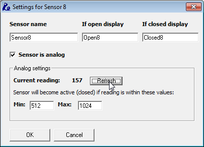
…like shown in the image. Clicking “refresh” will update the current reading. The goal is determining the range of values where we can consider the object is in its place. In our example, the mount is parked, so we could:
- unpark it – the sensor should read near 0 (less than 20) if properly placed, but other values could do, too;
- or move it toward the parking position, clicking refresh and taking note of the values.
In a few tries, we'll be able to know in what range of values the mount is in a safe position; filling with these values the “Min” and “Max” fields:
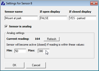
…the main Dragonfly window will update its display accordingly to the current position of the mount. As seen, we've also filled the rest of the fields (sensor name, etc), and used sensor number 8 as it is more convenient due to the ground plugs placement. There is a separate instruction sheet for wiring this kind of sensors, just check our website.
If you are going to use scripts with an analogue sensor, please read the corresponding addenda.
Addenda 2: relay restrictions
As requested by several users, we've added relay restrictions – meaning you can define certain conditions under which the relay won't open or close. This is performed from the relay settings window we partially saw a few pages ago.
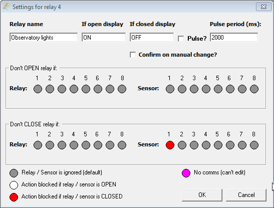
Clicking on each small circle, we can block the relay action (upper row, blocks opening; lower row, blocks closing) on each condition – relay or sensor open or closed.
In the above window, the observatory lights relay won't close if sensor 1 (roof open) is active – so if the roof is open, you won't be able to turn on the lights.
Two important notes about this:
- These restrictions are global, and imposed internally by the Dragonfly firmware. So, they work even if the action is commanded from a script, ASCOM, the web interface, smartphone app, or an internal macro.
- You can, however, circumvent it, by repeating the action in the 3 seconds period after trying for the first time.
- You click “close”, get the message “Ignored – restrictions”, click again, and then it will close.
- From scripts or macros, you can force any action by duplicating it.
5-d) Automated control – ASCOM Dome & switch
As previously mentioned, it is very important to be confident with the remote operation of the observatory before addressing any kind of automation.
Complete automation requires a bit more of effort; apart from the Dragonfly, we'll need some automation software (there are many in the market), automated focusing support, etc. – and, most importantly, everything running smoothly.
The ASCOM standard plays an important role here, as it enables different devices and programs to understand each other. In our case, the Dragonfly follows the ASCOM standard for domes, with its functionality reflecting that of a roll-off roof observatory, and also offers a switch interface.
Switch
ASCOM's switch interface is a convenient way of accessing the relays and sensors (inputs) of your Dragonfly from a third-party software. Just select the Dragonfly in the ASCOM chooser and you’ll be ready to control everything similarly to how you would from the Dragonfly software, but from inside this 3rd party program.
Dome control
Not so straightforward, but easy enough. Basically, thanks to the ASCOM standard, when our automation program wants to close the roof, the Dragonfly will be asked to do so. We will get three kinds of messages or requests from the automation program:
- Open the roof
- Close the roof
- Tell me the status of the roof
For each of these messages, the Dragonfly software will launch a script. All Dragonfly scripts are located in its home folder (usually “c:\program files\dragonfly”), under the “dfscripts” folder (that is, “c:\program files\dragonfly\dfscripts”). For 64-bit Windows editions, the correct folder is “c:\program files (x86)\dragonfly\dfscripts”.
Scared? — Don't be!
Scripts can be very simple if the actions they command are simple. There are sample scripts with the Dragonfly software, and we can help, even write scripts for you if you're stuck!
We have one script for each ASCOM message, so:
- Open the roof: OpenShutter.vbs
- Close the roof: CloseShutter.vbs
- Tell me the status of the roof: ShutterStatus.vbs
Programming the scripts can be a bit scary at first, but it is (or can be) simple indeed. Nevertheless, it involves thinking in advance and foreseeing possible situations.
On the plus side, scripts allow for full customization, and this is a big plus, worth the effort. For example, we can not only check if the mount is parked before closing or opening, but also command it to park issuing a few ASCOM calls from the script.
Let's work out the scripts for our sample observatory, leaving aside for the moment the park sensor, as it adds complexity and not everybody needs it.
So, what do we want the Dragonfly to do when requested to open or close the roof?
I'd say, for the open case:
- Check if it's already open, as in that case we don’t need to do anything.
- If it's not, then we need to push the roof control button, and wait for a period of time until the roof opens,
- if the period expires and the roof is still closed, we should issue a warning,
- if the roof successfully opens, we probably want the CCD and mount powered, and the lights powered off.
For closing the roof it is, of course, very similar.
Notes
Before going on, please bear in mind:
- We can't teach how to program in this manual; we will, however, explain things as clearly as possible so at the very least you can understand and modify the supplied scripts.
- Scripts are programs, usually simple ones but programs nonetheless;
- your computer will read the scripts line by line, taking actions as per the script commands.
If you are an accomplished programmer, well, you'll know what to do. There's a reference section a bit further in the manual.
If you need help, we will gladly assist to get your scripts running, and can even write them for you, as a free-of-charge service for our customers.
So let's start…
We just have to program (most probably we'll just use one of the examples, and maybe modify it) two scripts; one for opening, the other for closing the roof.
The one for opening is to be called “SyncOpenShutter”.
Here's a simple (slightly stripped down version of the script you'll find installed) but useful program; the lines in pink, indented to the right, are not present in the script, just added documentation here.
All lines starting with a single quote ' are considered comments
Write anything after the quote for documentation purposes
' Dragonfly SyncOpenShutter script
' (c) Lunatico 2016, 2025
'
' This will work “out of the box” if you follow the setup in the users' manual:
' - you have 2 sensors for open (sensor 1) and closed (sensor 2) roof
' - the roof motor is activated by a pulse, and its control is attached to relay 1
'
' Only thing you may want to adjust is the time allotted for the roof moving, currently at 120 secs
' The pulse for the motor is set at 2 secs (2000 milisecs) and should work in any setup
To avoid nasty errors, any variable we use should be declared first, so...
Option ExplicitNow we define a few numbers, that is, we give them a name, so the script is easier to understand
The relay and sensor numbers match the ones in the example we've been working through
' ASCOM Shutter State
const ShutterStatus_Open = 0        ' values from ASCOM standard, cannot be changed!
const ShutterStatus_Closed = 1
const ShutterStatus_Opening = 2
const ShutterStatus_Closing = 3
const ShutterStatus_Error = 4
' Own constants
' define your own constants here
const Sens_OpenRoof = 1
const Sens_ClosedRoof  = 2
const Rel_Roof = 1
const Timeout_OpenClose = 120000        ' 120 secs time for the roof to move
const RoofPulseLenght = 2000                ' 2 secs pulse for the roof "button"
…here we declare the variable Dfly (only one in this program) and set it as a Dragonfly “Help” object
Dim Dfly
set Dfly = CreateObject("Dragonfly.Help")
We'll use the “Dfly” object to “talk” with the Dragonfly.
Important: the first thing to actually do is notify we're opening the roof
df.AscomShutterStatus = ShutterStatus_Opening ' openingNow we'll check if it is already open
' check if already open
if ( df.SensorDigRead( Sens_OpenRoof ) ) then        ' sensor marks roof as open
        df.AscomShutterStatus = ShutterStatus_Open ' notify it is already open
        df.LogAddLine( "Already open!" )
        ' nothing else will be done
else
… in any other case – we assume it is closed, and simply go on
Call Dfly.RelayPulse( Rel_Roof, RoofPulseLenght ) ' pulse to the roof… sending a pulse to the roof.
wscript.sleep( Timeout_OpenClose )… and wait a reasonable amount of time (20 seconds)
before checking if it has opened.
        if ( Dfly.SensorDigRead( Sens_OpenRoof ) ) then
                Dfly.AscomShutterStatus = ShutterStatus_Open
        else
                Dfly.AscomShutterStatus = ShutterStatus_Error
        end if
Now we have checked the “open” sensor if it's opened,
update ASCOM to open, else to error
end ifAnd that's all!
And that's all needed to have our simple observatory automated using ASCOM. With these scripts, any ASCOM-aware program will be able to open, close, and report roof status.
Very important
The Dragonfly software will execute the scripts found in its install folder, “dfscripts” subfolder. If you program your own SyncOpenShutter.vbs and SyncCloseShutter.vbs scripts, you have to copy them to that folder, along with the supplied “OpenShutter.vbs”, “CloseShutter.vbs” and “ShutterStatus.vbs” scripts.
Also, if you don't follow the “roof open is sensor 1, closed is sensor 2” standard, you'll have to also tweak the “ShutterStatus.vbs”
The optional scripts for Relays and Sensor, explained next, also have to be placed in the same folder.
5-e) Automated control – on / off scripts
Additionally, more scripts can be programmed for the Dragonfly to launch, adding versatility. As you may have noticed in the control panel:

…you can enable / disable relay and sensor scripts. When enabled, and a change in the state of a relay or sensor is detected, the corresponding script will be launched.
These scripts complement the internal “macros” you can define using the Dragonfly Configurator. The main differences are:
- these scripts need this software (we're discussing here) running
- scripts can access other software on the computer – they can for example command the mount to park, launch programs, etc
- macros, however, will be active as long as the Dragonfly is powered and can be triggered by a variety of conditions
- macros actions are limited to changes in relays and a few network operations: sending emails and pushbullets, waking a computer via WOL, …
Check the exhaustive Dragonfly macros manual or our short tutorial videos for more information on the macro capabilities.
Back to the scripts, the naming convention is as follows:
- RelayClose1.vbs … RelayClose8.vbs: scripts to be executed when the given relay changes to closed.
- RelayOpen1.vbs … RelayOpen8.vbs: same, when it changes to open
- SensorOn1.vbs … SensorOn8.vbs: when the sensor changes to ON
- SensorOff1.vbs … SensorOff8.vbs: … and to OFF.
Only existing scripts will be taken into consideration, missing ones will not result in any kind of error – meaning if you want a script to run when sensor 4 becomes ON, you just have to write that one (SensorOn4.vbs) and enable sensor scripts. No problem at all with the missing scripts for other sensors.
A simple but powerful application is to have a physical button terminate the session – park the scope, close the roof, switch off the computer. Another possibility is to use one sensor input to detect power failures; there's an article explaining this on our website.
Important considerations:
- The scripts will be executed when (or if) a change is detected. Very fast or spurious changes may not be detected at all (this will depend on the refresh period configured).
- They will be executed just once for each change.
- Beware of script – script, and script – program interaction, for example:
- If your automation program is in charge of monitoring the weather, do not just close the roof if a sensor detects unsafe weather – but instead you can set it up so it closes if, after a safeguard period, it's still open.
- If you want to switch off the lights (or the dehumidifier) when the roof starts to open, do it in a single place, either at the ASCOM OpenShutter script (it will work only when opening via ASCOM) or with a sensor script when the sensor indicating “roof closed” changes to open (it will work as long as the Dragonfly software is running).
Don't forget that your scripts can do many more things than just handling the Dragonfly’s inputs and outputs – they can launch external programs, access any ASCOM objects (such as the mount), command Windows to switch off…
Addenda 1: analog sensors
Even if you have properly configured the analogue sensor settings as explained in the preceding section, that configuration will only affect the remote control panel (main window) of the Dragonfly.
For the sensors to behave as analogue in the scripts, the method “SensorAnRead” must be called, and the result (which will be between 0 and 1024) matched against the desired values.
6. Dragonfly functions
(they are properly called methods and properties)
All the examples assume the Dragonfly object was created using:
dim df
set df = CreateObject( “Dragonfly.Help” )
6-a) Functions to handle the relays and read the sensors:
Function | Description | Example(s) |
|---|---|---|
RelayOpen( relayNumber ) | opens the given relay |
|
RelayClose( relayNumber ) | closes the given relay |
|
RelayChange( relayNumber ) | changes the relay status, opens it if closed and closes it if open; if configured as a pulsed relay, it will pulse following that configuration. |
|
RelayPulse( relayNumber, period ) | Pulses the given relay for the specified number of milliseconds. Pulses it regardless of the control panel configuration. |
|
RelayRead( relayNumber ) | Reads if the given relay is energized / closed (TRUE) or not (FALSE) |
|
SensorDigRead( sensorNumber ) | Reads the given sensor digitally, that is, returns TRUE or FALSE. |
|
SensorAnRead( sensorNumber ) | Reads the given sensor analog, that is, returns a number between 0 and 1024. |
|
6-b) Functions to control the log output
These are useful to know what's going on!
Function | Description | Example(s) |
|---|---|---|
LogShow | Shows the log window |
|
LogHide | Hides the log window |
|
LogClear | Erases the log window contents |
|
LogAddLine( text ) | Adds the given line to the log window |
|
LogAddToLine( moreText ) | Appends the given text to the last written line |
|
LogUpdateLine( newtext ) | Changes the contents of the last line of text |
|
LogSetBold( TRUE or FALSE) | Sets or unsets the last line as Bold characters |
|
LogSetForeColor( color ) | Sets the color of the text written in the last line |
|
LogSetBackColor( color ) | Sets the background color of the text written in the last line |
|
The colors are RGB values, expressed as hexadecimal values, in this way: &H00BBGGRR&. Very much like with a 3 colour astroimage. Values go from 00 to FF, &H00FF0000& being a 100% blue colour, &H0000FF00& a 100% green one, etc.
6-c) The only ASCOM function – report the status of the roof
Function | Description | Example(s) |
|---|---|---|
AscomShutterStatus( status ) | Sets or reads the status of the shutter – this is accessible to other ASCOM programs. |
|
6-d) Advanced functions for asynchronous scripts
These are most likely not needed.
Function | Description | Example(s) |
|---|---|---|
timer( timerNumber ) | Reads or sets a countdown timer in milliseconds. Will stop counting when ≤ 0. It also sets “timerActive( timerNumber ) to TRUE” – but will not set it to FALSE when 0 is reached! |
|
timerActive( timerNumber ) | Gets or sets the active status of a given timer. Set to TRUE if the timer is started to count |
|
flag( flagNumber ) | User flag; can be read or written, to true or false |
|
UserVar( varNumber ) | Same as flags, but with integer (numeral) values |
|
Please take a look at the included sample scripts (explore your software folder, ffscripts, for a “samples” folder) for well documented, clearly written ones.
7. Network configuration
As received from the factory, the network settings will work in almost every case. Both the program and the Dragonfly are configured to take an automatic network address and work with it.
Either way, go ahead and press settings; you'll see these options:
Focusing on the “Connect…” sections:
- Controller address or name: just as any computer in your observatory network, the dragonfly has a name and an address. By default, its name is “Dragonfly” and its address will be assigned automatically. More on this later.
- Controller port: unless there's a problem, this should not be changed. You can think of ports as “channels” within the computer or controller – so the controller will be listening at channel (port) 10000.
- Local port: conversely, the port used by the computer. Leave it at 0 and a suitable one will be picked. You can force a specific value for special cases.
- The same applies to Network timeout (ms), this being the time the program will wait for a network response before assuming there's a problem.
- Zero Configuration Network: if you are using this software from a different network than the one the Dragonfly is sitting on, you can connect to our cloud server to, in turn, establish the connection to the Dragonfly.
- Recommended for laptop users on the move, or from the smartphone
- If the PC is sitting on the same network as the Dragonfly, do not use it – a normal, non-Zero Conf connection will be faster.
If you do choose to use ZeroConf, please note:
- The Dragonfly has to have been configured to connect itself (from the Configurator).
- Use your real email to avoid duplicities and help with system maintenance.
You have more information on it in the next section.
8. Zero Configuration Network
It works in the following way:
- Your Dragonfly, if so configured, will connect with our server and inform it of its network address. It will do this every 30 seconds.
- Your software, windows, smartphone, … , may connect to the server and ask for the address of your Dragonfly, in which case:
- first, a direct connection will be attempted (same network),
- if this fails, it will try a remote but point to point one (different network, but with well-behaved routers),
- and if this doesn’t work either, the cloud server will set up a relayed conversation, that is, it will sit in the middle and redirect all messages in both directions.
- These relayed conversations are quite costly – please reserve them for short connections (connect, check, open, close, etc, disconnect, a few minutes at most).
- We reserve the right to abort long relayed sessions, or even completely disable the relay system.
9. Final control tips
Never use fluorescent lights! They are one of the strongest sources of electrical noise.
Reed (magnetic) proximity switches are very useful to check for roof and mount position. Any will work with the Dragonfly. The inexpensive ones we've found the most reliable are the ones available from RS components with ref. 289-7783 (don't forget to get the magnet, ref. 289-7812).
If using push-buttons to detect roof position (such as RS ref. 746-8605), the usual way is to place the push-buttons in a fixed position (wall), and the part that will press them – a plastic angle is suggested, as it can bend and won't damage the push-button – in the moving roof.
The above sensor suggestions are some we've tested and confirmed worked fine under normal conditions. Also, properly configured, you'll get an error from the software in most failure cases. It may however be reasonable to go for high-quality ones in truly remote observatories or with very expensive equipment. It is difficult nowadays to separate the good quality from the not so good, but no doubt very good sensors are readily available.
Plan carefully, be redundant if at all possible, and have a UPS strong enough to close the observatory in case of power failure.
A simple external relay can be used to detect power failures and maybe force closing the observatory. These and many more useful tips are available on our “more information” webpages.
Every Dragonfly has an internal web – it can be used to get system information, check sensors and change relays, comprobar sensores y cambiar relés, y actualizar el sistema en el caso del Dragonfly 2. It can be accessed by simply pointing your internet browser to the dragonfly address, by default: http://dragonfly.
10. Appendix
10-a) Dragonfly technical specifications
- Power requirements: 12V dc, center positive, standard 5.5 – 2.1mm power jack, less than 1A drawn. Dedicated power supply strongly recommended.
- External interface: 10/100 Mbit ethernet – TCP/IP v4
- Microcontroller: AT91SAM7XC256 + a model B Raspberry Pi for Dragonfly 2.
- Relays (8):
- Nominal switching capacity: 10A @ 125V/250V y 6A @ 277V
- Max. switching voltage: 250 V AC, 100 V DC
- Max. switching current: 10 A (AC), 5 A (DC)
- Model Panasonic JS1-5V-F
- Inputs (8):
- protected with Littelfuse 600R160UR resettable PTC
- all 8 capable of analogue and digital readout
- Aluminium folded box, connected to earth via any of the 16 earth plugs.
10-b) Reminder!
The configuration of the Dragonfly unit itself (its network name, port, if using ZeroConf or not– see below, ... ), are managed from the separate tool “Dragonfly Configurator”. There is a separate user manual for this tool.
The configuration changes we do to the software we are explaining in this user manual will affect this – and only this – software.
As an example, renaming our dragonfly to, say, “halfsky” typically involves two steps.
1. With the “DragonflyConfigurator”, rename the unit. Once it reboots, it will use the new name
2. To new connect to it, we will have to change the name in settings in this window software (“control panel”). Similarly, if we connect from a web browser, we will need to use the new name.
11. Edition history
1.2 Initial public release
1.3 Improved explanations in the properties and methods section
1.4 Added this history section
1.5 Fixed the power jack specifications
2.0 Added Dragonfly 2, and software 6.0 – many changes
2.1 General corrections
2.2 General clean-up and small details on macros added
2.3 Software v7.0 updates, minor updates and clean-up