
Supplied material
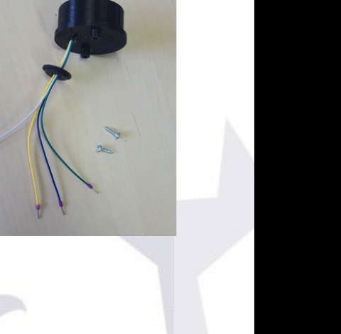
- Relative humidity and atmospheric pressure sensor, wired and protected.
- Screws (2 ud.)
Aside from the supplied material, you will need:
- Your CloudWatcher unit (CW).
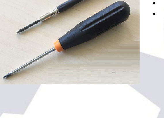
- A flat-head screwdriver.
- A Phillips screwdriver.
- A bit of glue.
1st step
Remove the knurled nut in the back of the CW and softly separate both sides of the box.
Unscrew the PCB board. Be careful to avoid damaging the insulating product that protects the board.
Separate the PCB without pulling the wires.
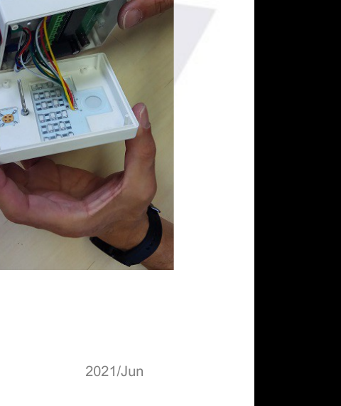
Once the back of the box is separated, insert the sensor cables through the first ventilation hole, as shown in the image.
It is crucial that you keep the upper part of the CW, which contains the IR and rain sensors, protected for as long as you are manipulating the unit. All you need to do is place them over a soft cloth or a paper napkin.
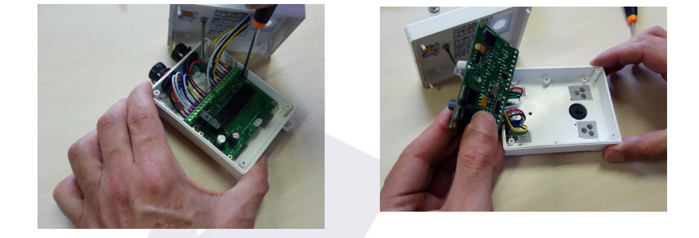
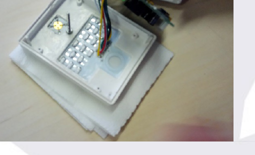
Remove the protective lid from the back, putting pressure on it with your finger.
2nd step
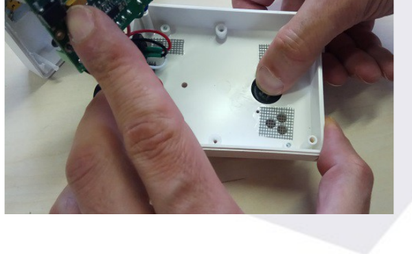
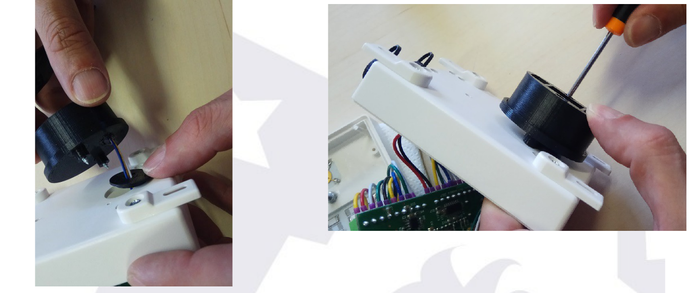
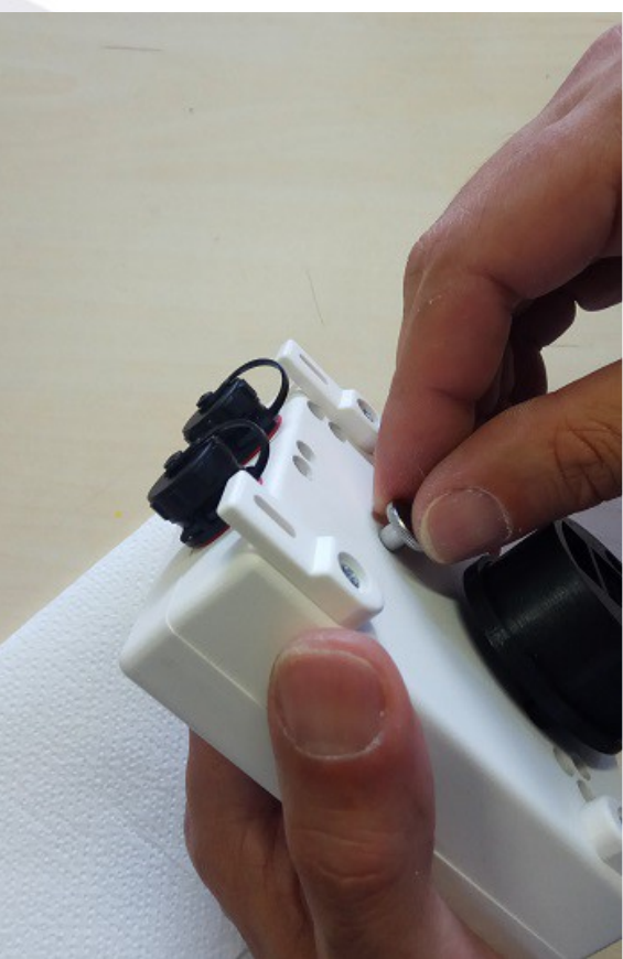
Prepare the sensor: introduce the screws in the two round holes until the tip appears on the back of the cover.
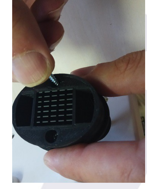
Insert the supplied set into the hole, as shown in the image. Apply a bit of glue to the inner part of the round piece in order to ease its attachment to the box.
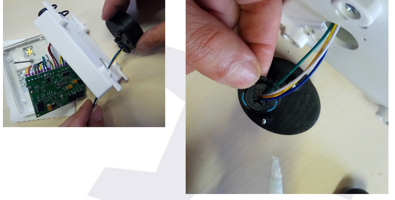
Place the sensor in its position, attach the round piece to the hole, and screw in the sensor to the box firmly.
3rd step
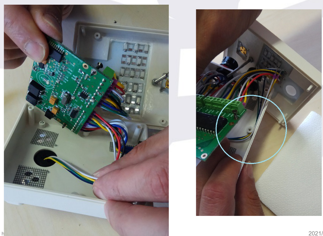
Guide the wires through the right side of the inside of the box, hooking them to the side, as shown in the image.
It is important to do it on this side of the box in order to minimise the amount of heat that gets to the wires from the components of the main unit of the CW.
4th step
Screw the PCB to the box again.
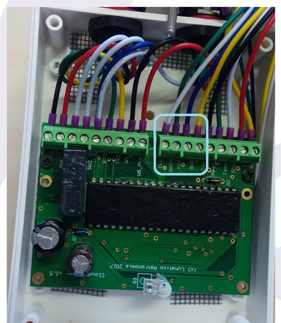
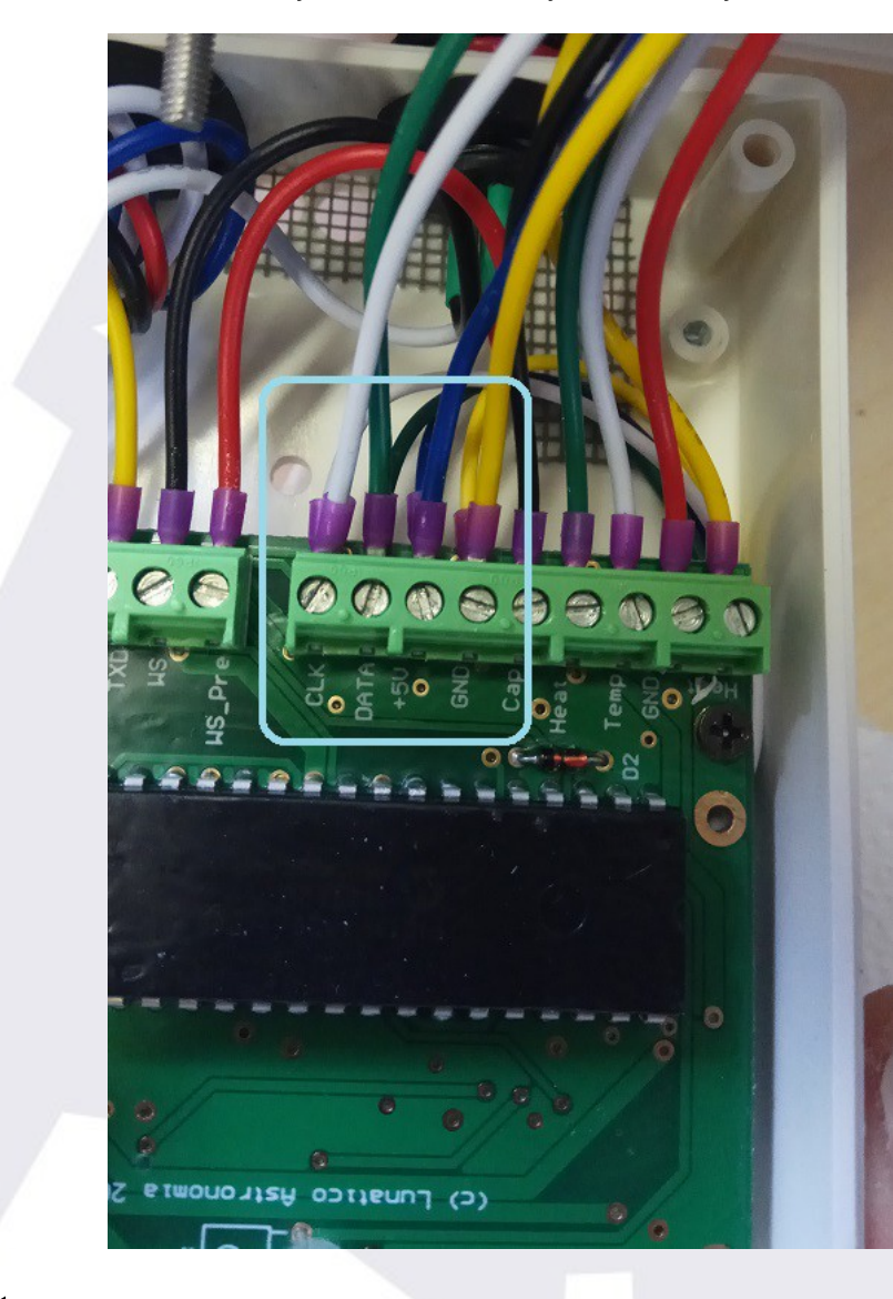
Now is time to connect the sensor wires to the main board of the CW. It must be done in the holes that are located in the middle of the board and follow this order:
- White (CLK)
- Green (Data)
- Blue (+5)
- Yellow (GND)
Unscrew the first wire and introduce the point of the corresponding colour in the hole. Screw again.1 Repeat the operation with the three remaining cables.
1 Sometimes, when loosening the screws in the green terminal plugs, the part that holds the cable does not move—so the cable is not freed. In this case, press the screwdriver firmly on the screw, give a sharp (but light!) blow downwards on it until you hear the "click", and unscrew again.
Pull the wires softly to make sure they are correctly attached to the board.
5th step
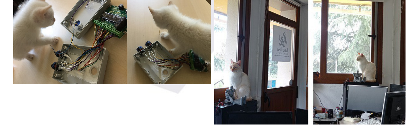
Look at how the cat has grown…
6th step
Lastly, close the box and screw in the knurled nut.
7th step
Install the firmware version 5.8.6. All the software and other downloads for the CloudWatcher are available on our downloads page, or from our forum.