
Finding the serial number: from the computer, see the "Device" tab, in "Constants Section" is the first data. From the SOLO, use http://aagsolo/cgi-bin/cgiLastData (if you don't see it, update the version first).
Material supplied
- Relative humidity sensor, wired and protected. We will call it RHS.
- Quick splice connectors (4 ud. + 2 extra).
- Screws (2 ud. + 2 extra).
Assembly in units with serial number 400 to 1205
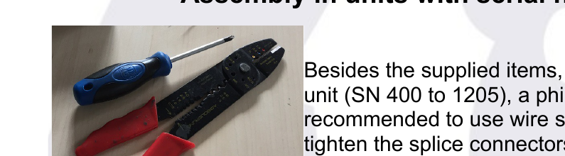
Besides the supplied items, you will need your AAG CloudWatcher unit (SN 400 to 1205), a Phillips screwdriver, and it is recommended to use wire strippers or at least some pliers to tighten the splice connectors.
A-1st step
Unscrew your AAG CW, first the white box and then the PCB board. Be careful to avoid damaging the varnish and the insulating product that protects the board.
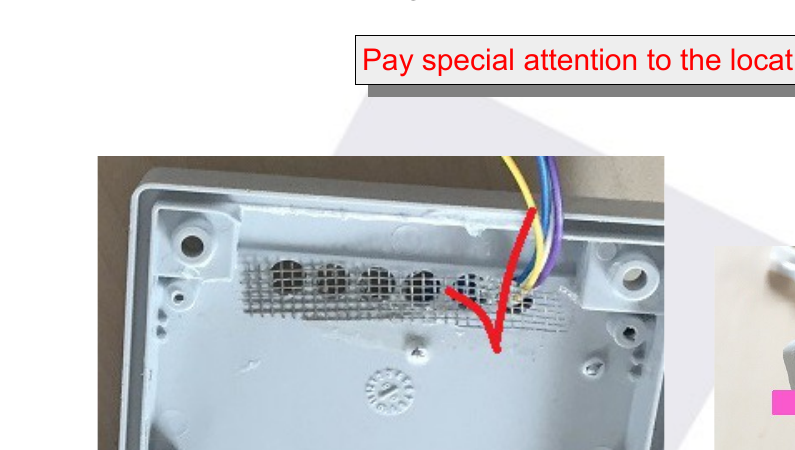
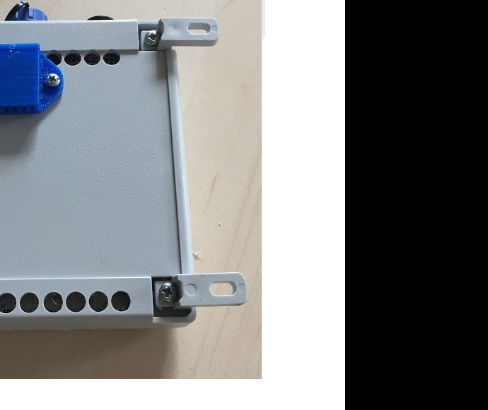
Once the back of the box is separated, insert the sensor cables through the first ventilation hole, as shown in the image.
Pay special attention to the location of the holes!
Place the sensor in position and screw it firmly to the box.1
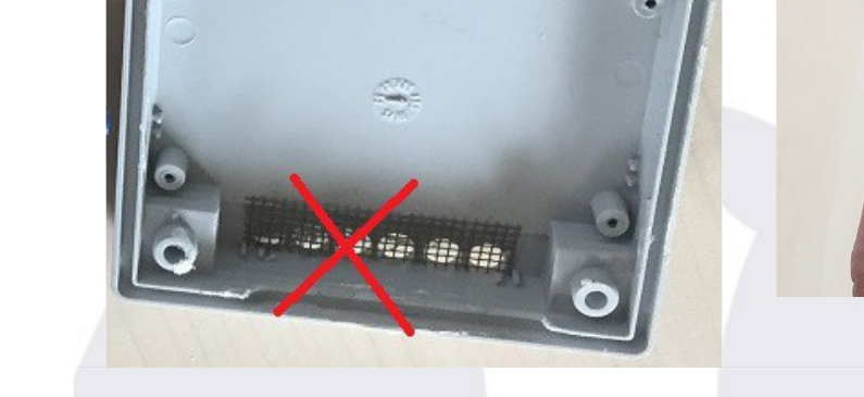
1 A power screwdriver makes this operation easier, but it can be done manually. Two extra screws are included in case one gets "jumpy".
A-2nd step
Check the colour code of the IR sensor of your CloudWatcher (the 4 cables that come from the upper end)—the colours should be as in the image, that is:2
- Violet (or Green) (Data)
- Blue (+5)
- White (CLK)
- Yellow (GND)
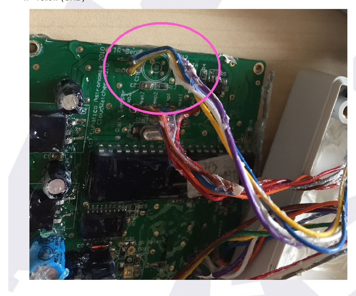
2 If your unit is of the 700 series (No. 700 to 799), the wires will have a different code: 1. Yellow (Data), 2. Violet or Orange (+5), 3. Blue (CLK), 4. White (GND). And the connections should be: Yellow PCB with cable Violet Sensor; Violet PCB with Blue cable; Blue PCB with cable White; White PCB with Yellow cable. In case your unit has a different colour code than these described, please contact us before making the connections.
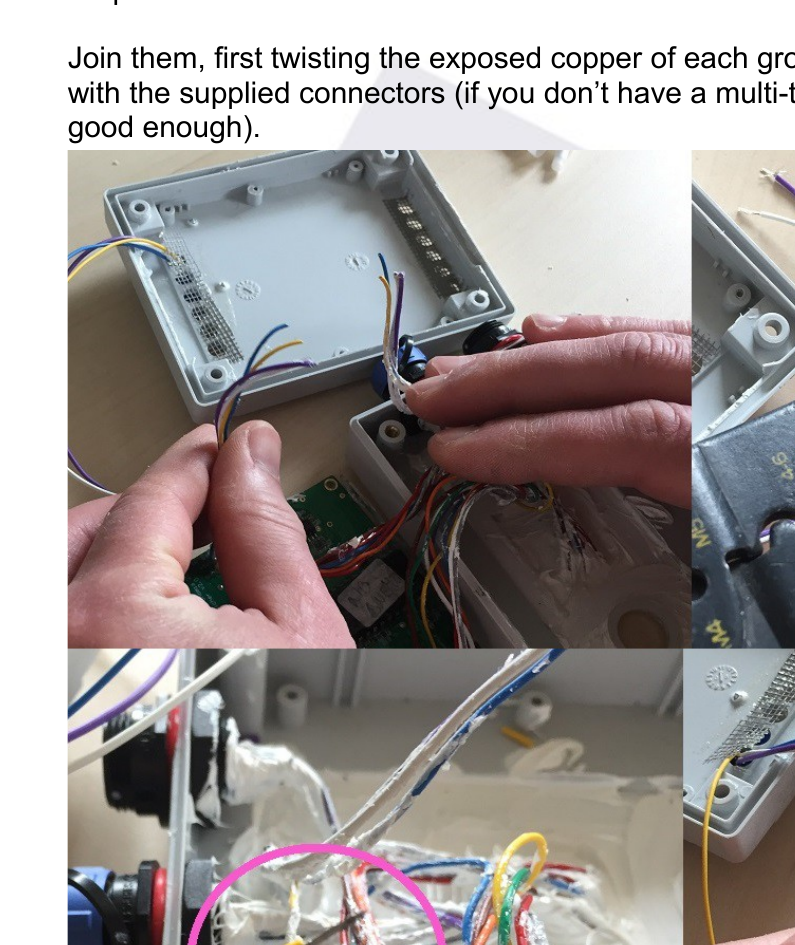
Cut the cables (at approx. half length) and place them alongside the ones of the new RHS. Strip each cable for about 10mm or ⅜".
Join them, first twisting the exposed copper of each group of 3 cables of the same colour, then with the supplied connectors (if you don't have a multi-tool as in the image, some pliers are good enough).
A-3rd step
Check that the anti-insect grid is properly positioned or, if needed, glue it again to the box.
Place the PCB in the box by routing the cables over it.
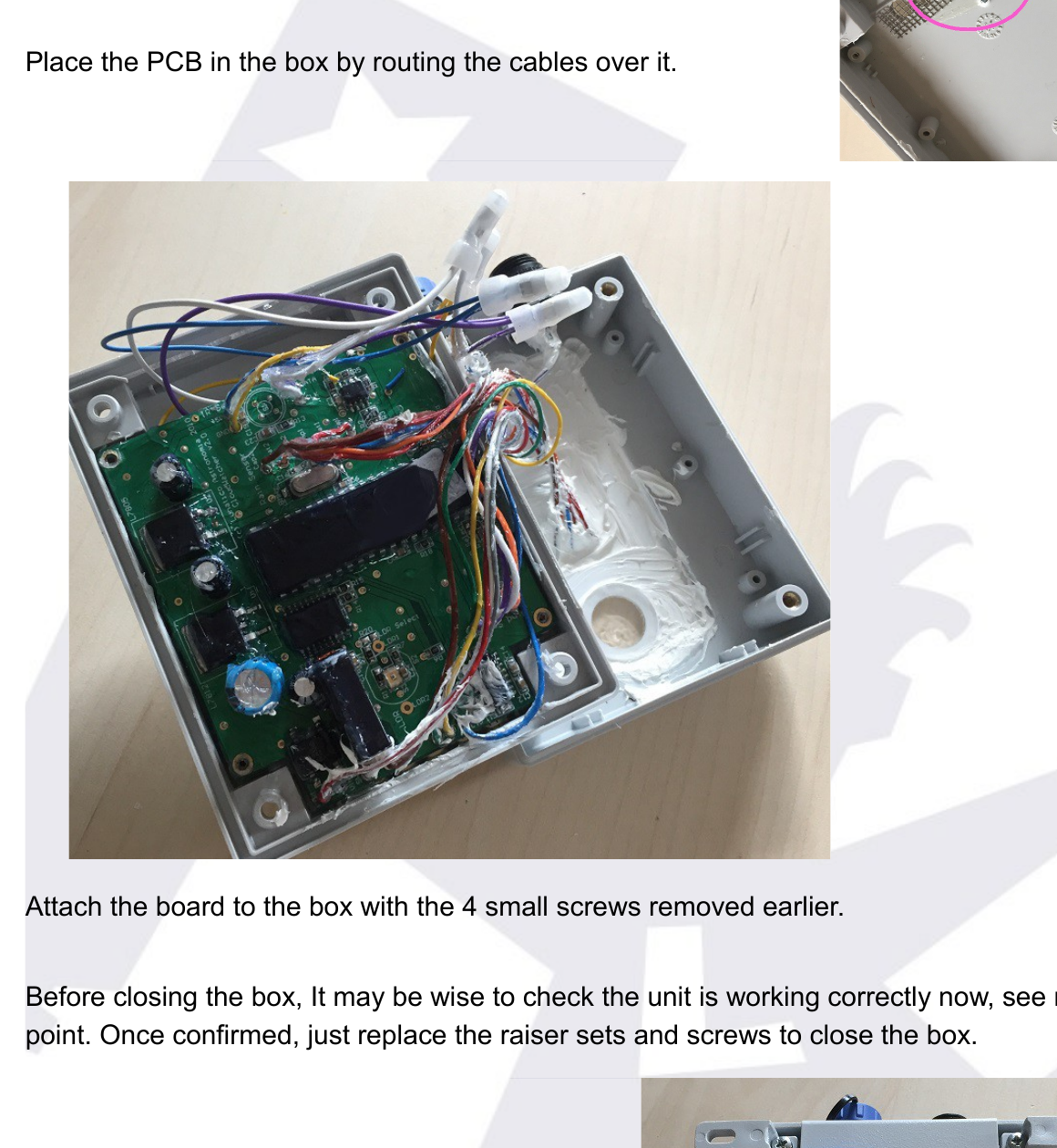
Attach the board to the box with the 4 small screws removed earlier.
Before closing the box, it may be wise to check the unit is working correctly now (see next point). Once confirmed, just replace the riser sets and screws to close the box.
A-4th step
Update the unit firmware (it will need version 5.7) and software from our downloads page.
Assembly in units with serial number 1206 onwards
If your unit is number 1206 or higher, you will need three screwdrivers: one regular size Phillips, and two small ones—flat and Phillips.
B-1st step
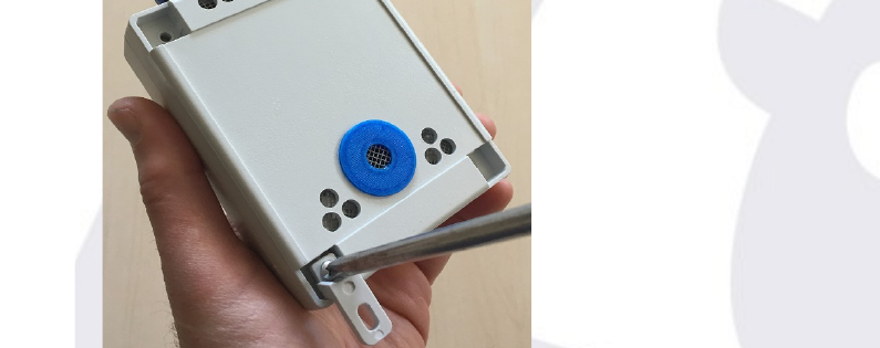
Remove the screws from your CW box and then the blue washer from the back (it is glued with putty and should be easily released—just insert the tip of the flat screwdriver and bend a bit).
Once the box is opened, remove the screws holding the PCB (board) carefully, removing the minimum amount of varnish and the anti-humidity product that protects the board. You must remove the 4 screws from the board and the one that fixes the voltage regulators to the box.
B-2nd step
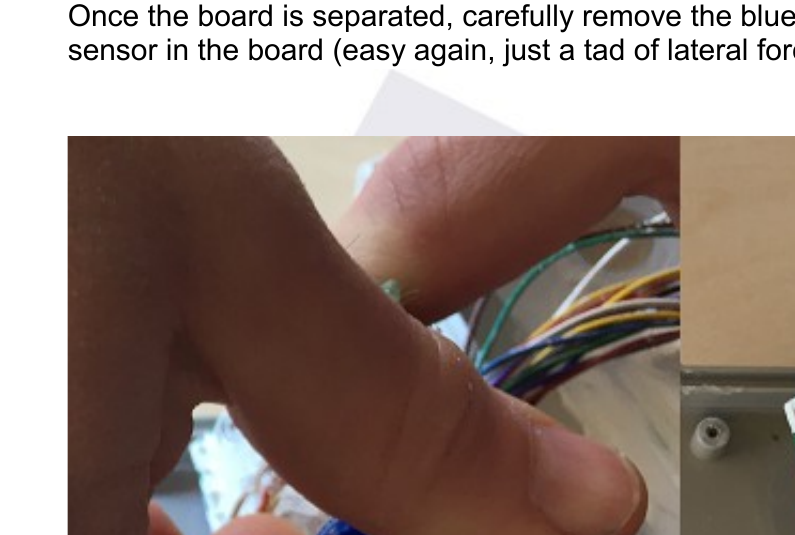
Once the board is separated, carefully remove the blue separator that protects the humidity sensor on the board (easy again, just a tad of lateral force).
B-3rd step
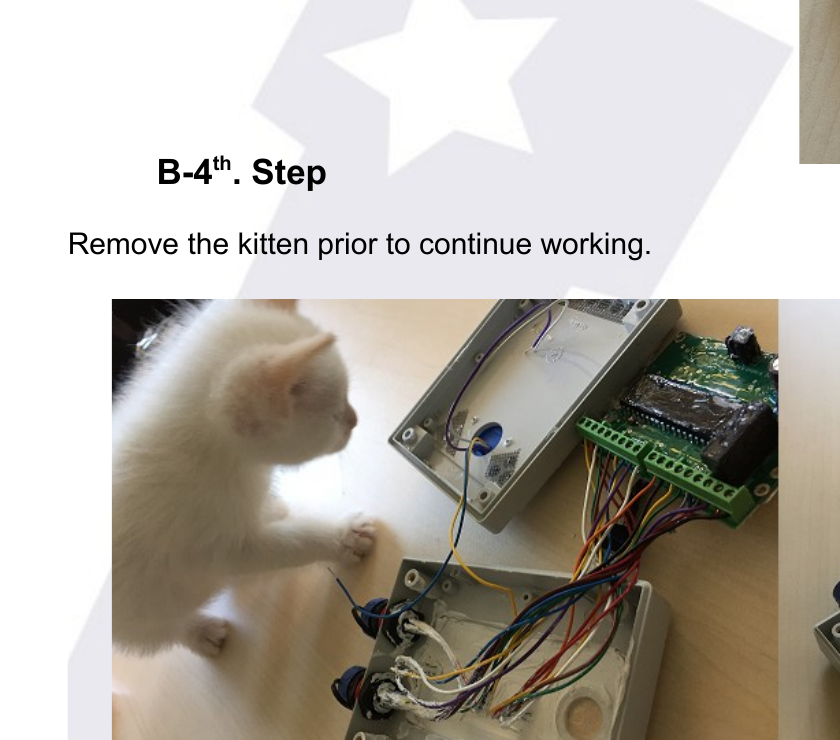
Insert the RHS cables through the large hole that has been left free, as shown in the image.
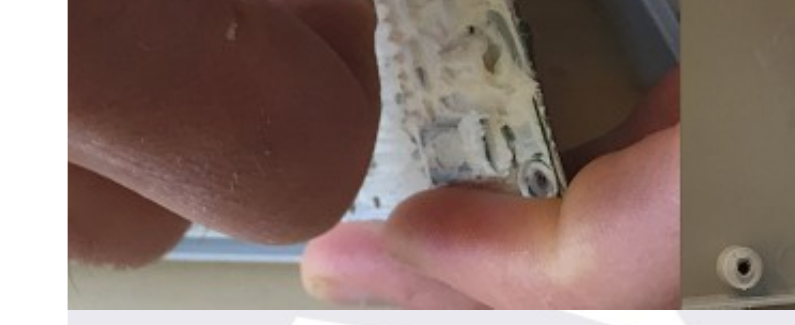
Place the sensor in position and screw the piece firmly into the box.3
3 A power screwdriver makes this operation easier, but it can be done manually. Two extra screws are included in case one gets "jumpy".
B-4th step
Remove the kitten prior to continuing working.
B-5th step
It is time to join the RHS wires with the AAG IR sensor; they are towards the middle of the board and follow the order:
- White (CLK)
- Violet (or Green) (Data)
- Blue (+5)
- Yellow (GND)
Unscrewing each colour, join the wires (first twisting together the exposed copper), insert them in the corresponding hole and screw again.4 Gently check that the cables are firmly fixed to the PCB.
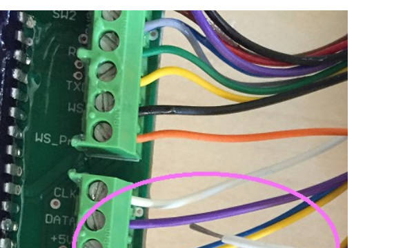
Very important: units 1206 to 1226 have the green connectors varnished, so the cables cannot be unscrewed. Instead, cut them and join with the connectors, as shown in Step A-3rd.
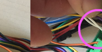
4 Sometimes, when loosening the screws in the green terminal plugs, the part that holds the cable does not move, so the cable is not freed. In this case, press the screwdriver firmly on the screw, give a sharp (but light!) blow downwards on it until you hear the "click", and unscrew again.
B-6th step
Finally, screw the PCB back to the box (do not forget the voltage regulators) and place the back cover with its screws and washers.
Before closing the box, it may be wise to check the unit is working correctly now (see next point). Once confirmed, just replace the riser sets and screws to close the box.
B-7th step
Update the unit firmware (it will need version 5.7.3 AAG and minimum version 2.0 SOLO) and software from our downloads page, or from our forum.