
These instructions cover current units. If yours is older, check whether your unit falls in the serial number range 400–1206 or 1206–2400 instead, as the procedure differs slightly.
What do you need?
- An electric screwdriver.
- A flat screwdriver.
- A glue gun with hot glue (if needed).
Steps
- To safely install the sensor, please remove the board from the box by disconnecting the cables. This will leave you with the box bottom only, as below:
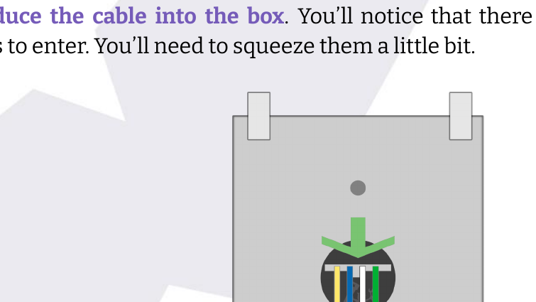
- Introduce the cable into the box. You'll notice that there is small room for the cables to enter. You'll need to squeeze them a little bit.
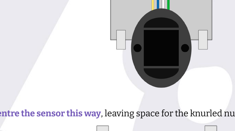
- Centre the sensor this way, leaving space for the knurled nut above it:
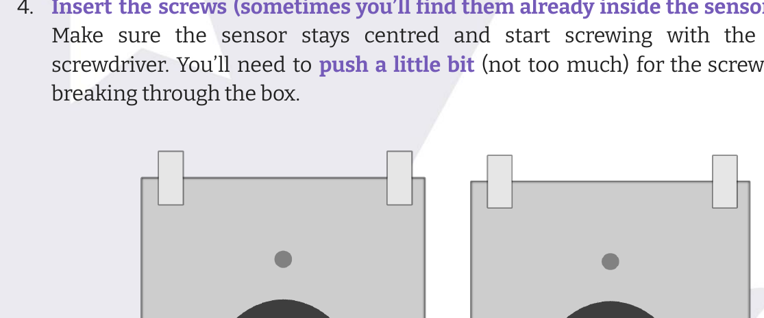
- Insert the screws (sometimes you'll find them already inside the sensor holes). Make sure the sensor stays centred and start screwing with the electric screwdriver. You'll need to push a little bit (not too much) for the screw to start breaking through the box.
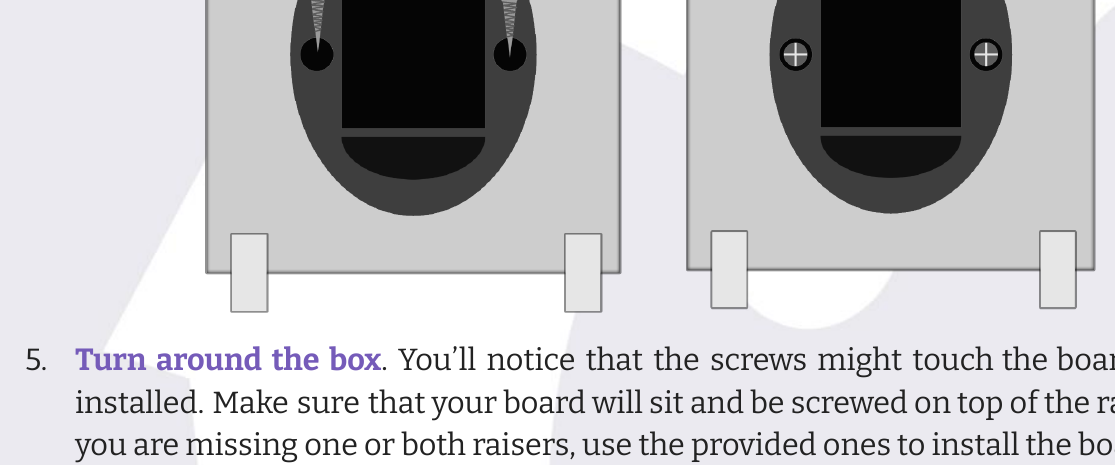
- Turn the box around. You'll notice that the screws might touch the board when installed. Make sure that your board will sit and be screwed on top of the risers. If you are missing one or both risers, use the provided ones to install the board—you can glue them with Loctite® or any other equivalent glue. If you have access to it, please use the glue gun with hot glue to cover the screw tips. This way you'll avoid any short circuit caused by the screws.
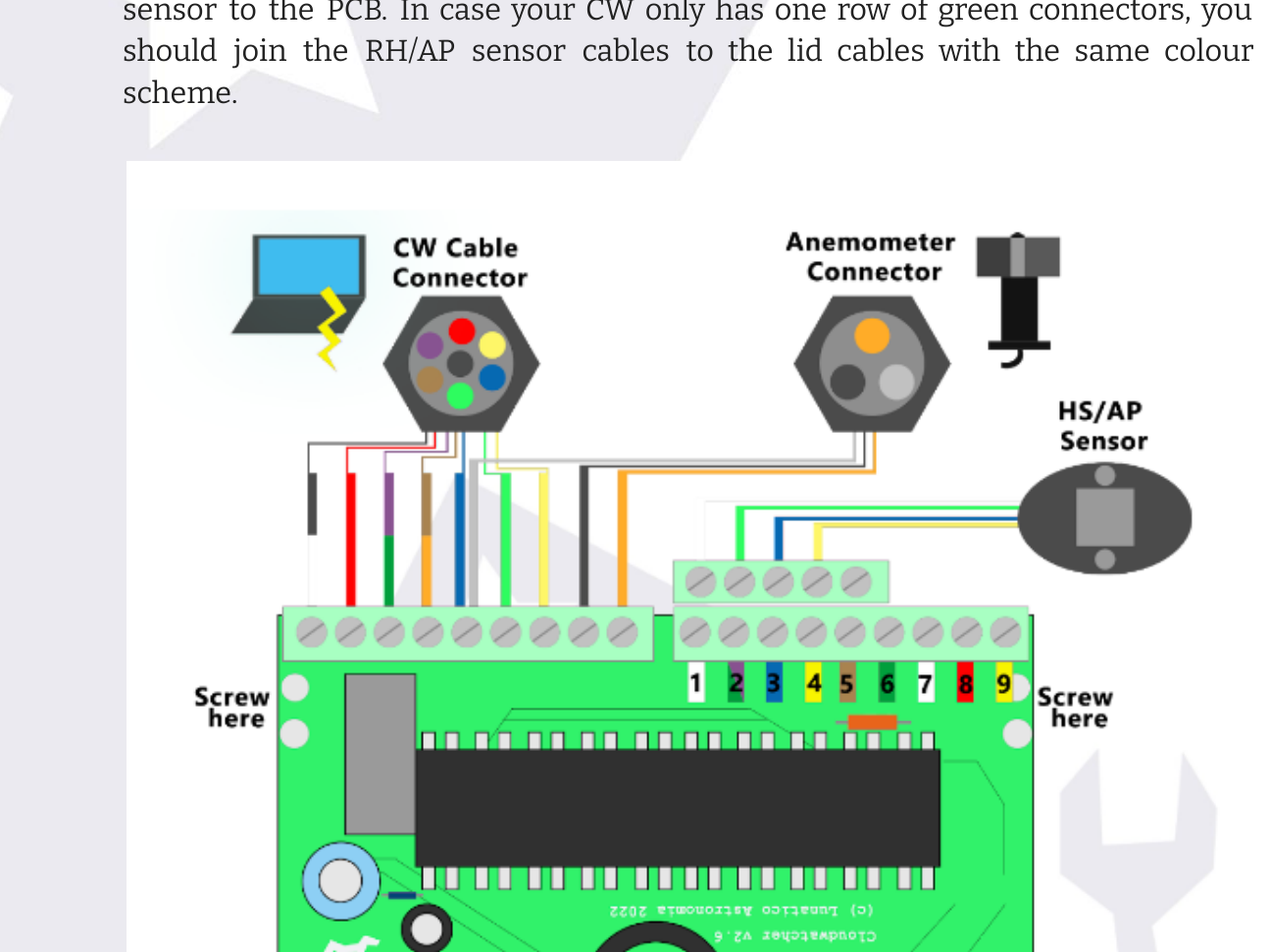
- Connect the sensor to the board. Follow this scheme to properly connect the sensor to the PCB. In case your CW only has one row of green connectors, you should join the RH/AP sensor cables to the lid cables with the same colour scheme.
Things to consider
- There are different board versions. When connecting the sensor to the board, you may find two different connectors: single row or double row. The single row connectors are the "older" ones, while the double row ones are "newer". Follow the scheme showing yours.
- Cable colours may vary. Sometimes cables are not available in the same colours as we previously used, resulting in a change of colour. We have included the most common colour changes (i.e. brown and orange), but if you have any questions regarding your cables in particular, don't hesitate to ask us at support@lunaticoastro.com!
- Avoiding the screws making contact with the board. To avoid short circuits caused by the screws used to fix the sensor to the box, please make sure that:
- Your board has risers to have a safe gap between the screws and the board.
- Use the provided risers if you are missing them.
- Use hot glue (or another method) to safely isolate the screws from the board.
- Centre the sensor and leave a gap for the nut. Your sensor will fit better into the CloudWatcher mount if it's properly centred. Also, leave a gap between the sensor and the nut that ensures the closing of the CloudWatcher.