Introduction
After one year of operation with a custom-designed environmental chamber for the CloudWatcher's external sensor PCB, the results are in: the robustness and performance of the design has been sound, and the accuracy of both temperature, pressure and humidity readings has been much improved compared to the original enclosure.
Background
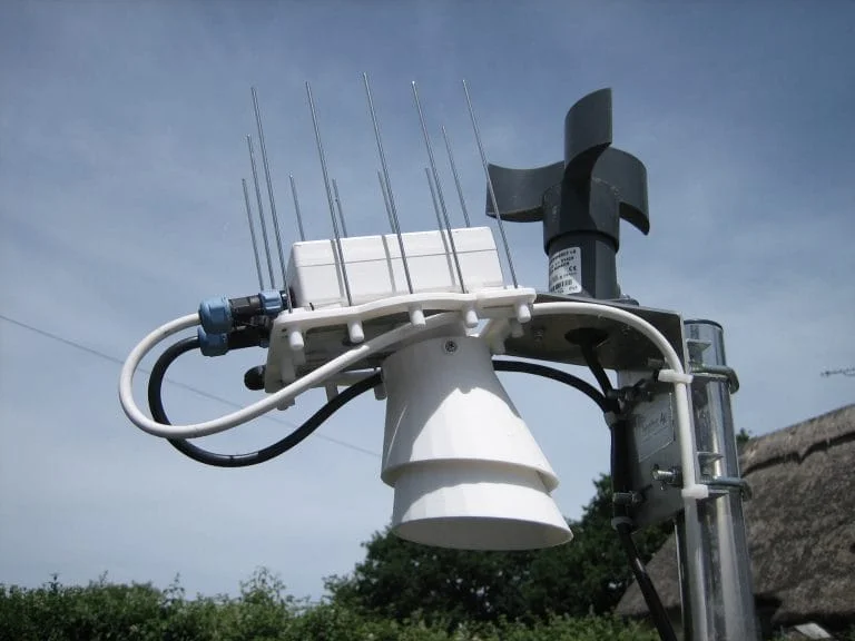
The original v1 and v2 CloudWatcher enclosures had issues with water ingress in heavy rain. After prolonged rainfall, humidity readings would stick at 100% for up to three days: the sensor was saturated from water getting into the chamber. Temperature readings also ran 5 to 6 degrees C above reference measurements due to insufficient ventilation and thermal isolation from the main enclosure.
The original discussion and design files are on the Lunatico forum.
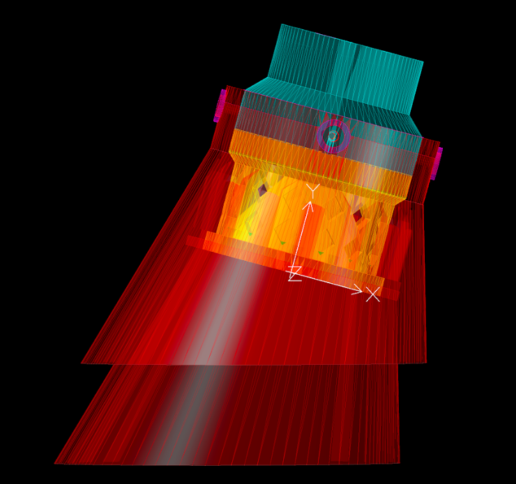
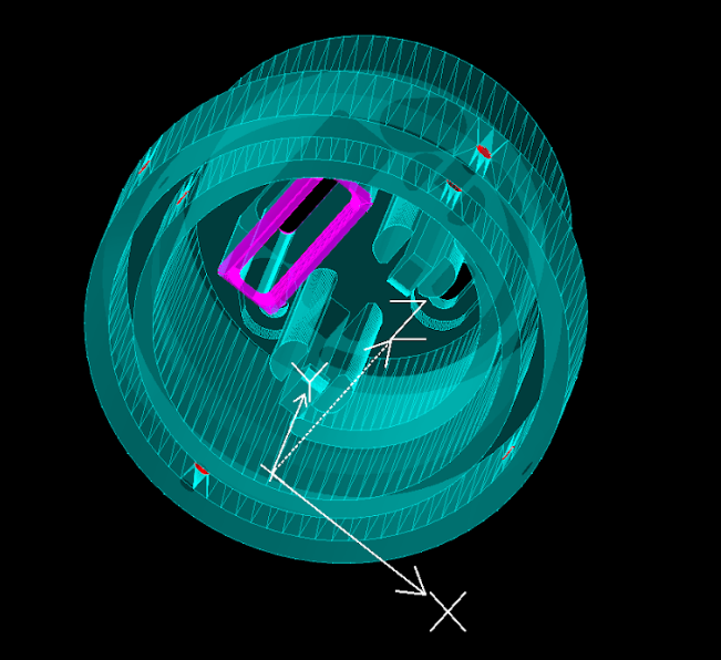
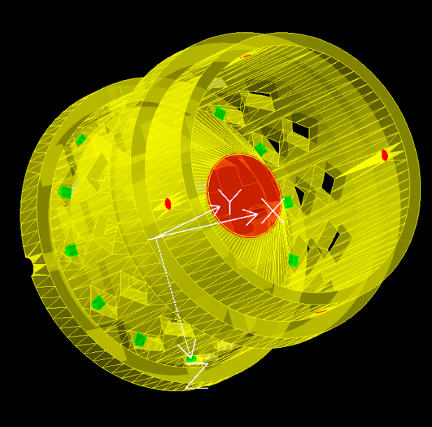
Environmental sensor chamber
The new chamber was prototyped in ABS filament using standard FDM 3D printing settings:
- 0.4 mm nozzle
- 60% infill
- ABS filament (for UV and temperature resistance)
The design includes an anti-bird spike platform to prevent birds from perching on the sensor, a practical addition for outdoor observatory installations where bird activity is an issue.
STL files available: The design files for 3D printing are available for download. See the forum thread for the latest files and print instructions.
Results—measured data
The following charts from the forum thread document one year of comparative measurements: temperature and humidity readings before and after fitting the chamber, along with pressure accuracy data.
Good news if 3D printing isn't your thing: Lunatico now ships a third-generation official external sensor chamber, with the PCB mounted on a heat-sink package, so you don't need this DIY mod on current units.