
1) Wiring
We supply the sensor with longer cables for your convenience. Please note the colour near the tip of each cable: one should be green (and/or) blue (ground), another red (and/or) brown (+5V), and the last one white (sensor out).
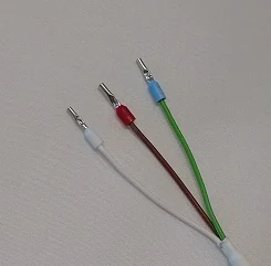
The ground one (green/blue) has to go to one of the 4 ground plugs (placed to the right of "sensor IN – 8"). The red and white will go to a normal "sensor"—for convenience, it is suggested to use sensor 8; so, red to sensor 8 +5V, white to sensor 8 In, blue to ground.
However, depending on your setup (sensor placement, mainly) you may want to avoid having it working all the time. In this case, wiring the +5V through one of the relays is the solution. You'll need an additional wire from "sensor 8 +5V" to a "power input In", and then the sensor's red-tipped wire will go to the matching "power output NO".
Don't forget to close the relay before reading the sensor!
2) Sensor placement
There are many options for placing the sensor, depending on your setup. Most important to know is that it will work better if the beam of IR light is aimed at a bright white surface (such as the scope OTA, maybe with a bit of photo paper attached if the distance is big enough, or a counterweight…).
Place it, adjust its position until the reading is maximized, then move the scope to be sure the reading drops when the scope is not in place.