
This should cover most needs, and be clear enough that changes can be easily made.
Also, please note we'll be focusing on the wiring and physical installation details, things not deeply addressed in the user's guide. For software configuration and other topics, have the user's guide handy.
Be warned: some of the steps here involve wiring things that will carry mains electricity—if you don't feel 100% comfortable doing so, seek the advice of a qualified electrician.
Tooling
We'll be doing very basic operations, and all can be accomplished with just cutting pliers; a cable peeling (stripper) tool will be nice to have, too. Other than that, just a small flat screwdriver (for the Dragonfly terminal plugs), and whatever you may need for installing the limit switches and distance sensor.
Initial steps
First of all, we have to decide where the Dragonfly is going to be installed. There's no need for it to be close to the scope, but to avoid needing very long power cables, a nice place is probably near the scope pier. All cables are going to converge at this place, from the limit switches, power, network cable, etc.
Before starting to install and wire all the peripherals the Dragonfly will be controlling, connect it to the network and power (12V d.c.), and check you can open and close relays using the software. Please refer to the Dragonfly user's manual if you need advice regarding this.
Roof position sensors (limit switches)
This is very observatory-dependent; we need to have one switch active (closed) when the roof is open, and another switch active when it is closed.
Note: it's also possible to have your roof open to certain points using macros and more switches—check the macros manual and ask us if you need help!
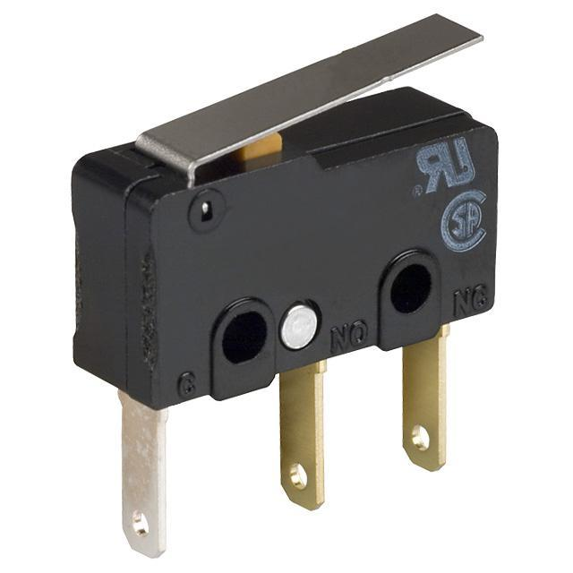
You can use whichever kind of switch you prefer; we favour the magnetic, contactless ones, but other types will do, too. This kind of switch (there are many versions) is quite nice, as it provides some play and thus doesn't require exact roof positioning. If you were using this model, connect the wires to the common (C) and normally open (NO) contacts:
Our magnetic switches are supplied standard with a 3 m cable (you can ask for different lengths to tidy things up):

Install both limit switches, connect the "roof open" switch to "sensor in 1", "roof closed" to "sensor in 2". By the way, no polarity—you can connect any switch wire to any of the "+5" or "In" plugs in the Dragonfly:
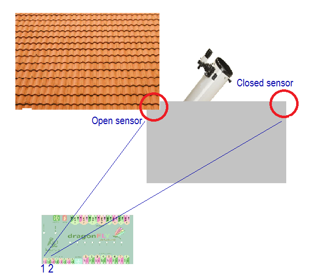
With the software, confirm that sensor 1 becomes active when the roof is open (inactive otherwise), and likewise for sensor 2 and the roof closed.
Mount position sensor
Again, you can use any sensor of your preference; for this guide we are going to use the Sharp IR distance sensor. Find a convenient place for the sensor—in my case, and many others, just checking the mount counterweight position is enough for roof safety, so I placed it on the pier.
Wiring it is really simple; just note the colour near the tip of each cable:
- one should be green and/or blue—ground,
- another one red and/or brown—+5V,
- and the last one white—sensor out.
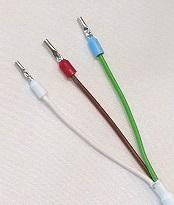
The ground one (green/blue) has to go to one of the 4 ground plugs (placed to the right of "sensor IN – 8"). The red and white will go to a normal "sensor"—for convenience, it is suggested to use sensor 8. So, red to sensor 8 +5V, white to sensor 8 In, blue to ground.
Now it's time to calibrate the sensor—please refer to the "Remote control" addenda, "analog sensors", in the Dragonfly user's manual.
Roof motor
Our roof motor should have the option of a wall-mounted switch to manually open and close it—push to activate, it will open or close alternatively each time. Instead of the wall switch (or in addition to it), we'll have the Dragonfly in charge.
Again, very simple: both wires from the motor system will go to the "power out", relay 1 (using COM and NO, again no polarity). On the input side, as we are not powering the roof motor (it is to be powered independently of the Dragonfly), but just activating it, pushing a button, we'll short a terminal plug:
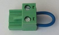
This way, when we close the relay, the circuit will close and the roof will start moving:
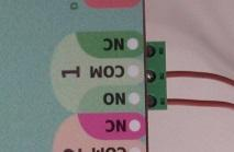
With the software, configure this relay as "pulsed", with any reasonable period (2 seconds, that is, 2000ms, works nicely).
Other devices
Wiring the rest of the items we want to control is pretty much the same for all of them, with a little exception for the observatory lights. For each of them we'll cut the AC cable and wire it, both sides, to the Dragonfly.
If you don't like the idea of cutting the power supply wires (voiding the warranty in the process), it's easy to make a Dragonfly-controlled plug for each device instead—see "Another way of setting up things" below.
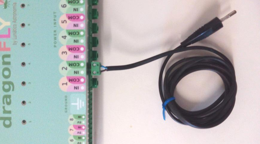
Once cut, the wires from the plug side will go to the "power in" of the Dragonfly, the other part, attached to the power supply, to the power out. The cable colour codes vary from country to country, but commonly:
- protective earth (or protective ground) will be green/yellow striped
- neutral either blue or black
- phase brown or red
Note: in case of doubt, please check en.wikipedia.org/wiki/Electrical_wiring.
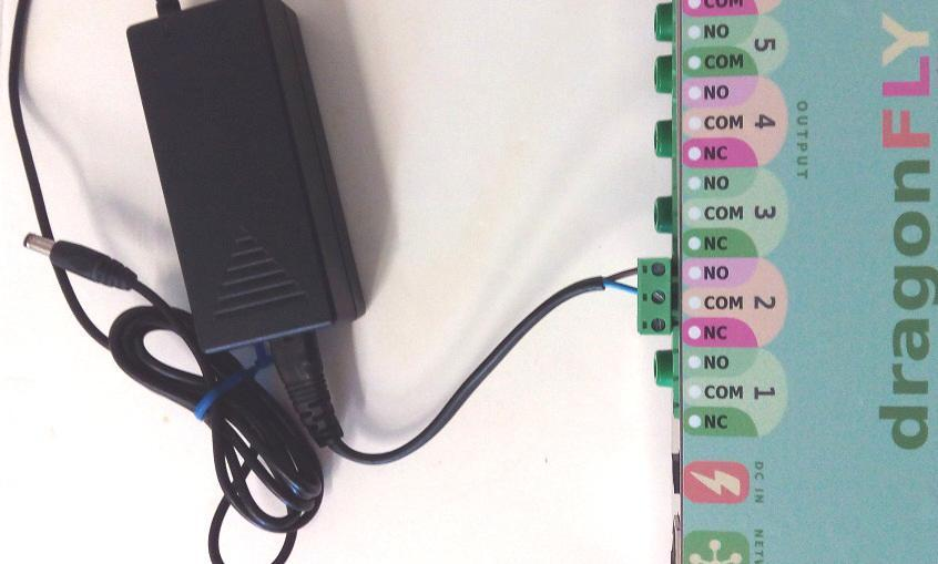
We'll wire neutral to common (COM), phase to IN (input side) and to NO (output side). If there's no ground, as in the power supply image below, no problem—at least one device should have it, to have the Dragonfly itself grounded:
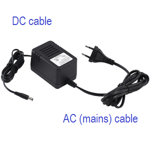
Do the same for all devices, so the relays are wired:
- to roof open / close button
- mount power supply
- CCD camera power supply
- roof / observatory lights (see note below)
- automatic focusing equipment
- fans (mirror cooling)
- flat foil (included in the Snap Cap)
- scope cover (Snap Cap)
By the way, for devices with earth / protective ground, to have all 3 wires align properly, cut the neutral and phase ones at least 70mm long, and the earth one 15mm shorter.
Relay 4, being the lights, is the exception to the rule, as we want them off while the scope is working, so instead of wiring the phase wire to NO, just wire it to NC:
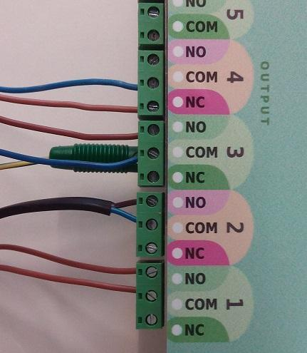
Image taken just after wiring the observatory lights—note the COM-NC connection, as opposed to the rest of the relays. Also notice the grounded (earthed) connection in the power supply at relay 3. All protective ground inputs and outputs are shared and connected to the box of the Dragonfly.
Another way of setting up things
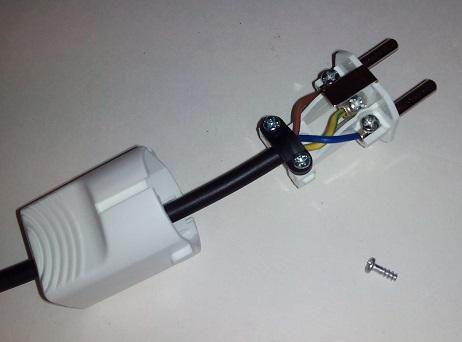
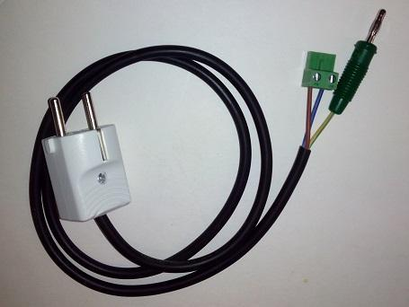
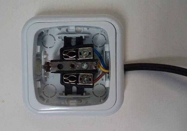
Instead of cutting the power supplies of the different devices, you may prefer to wire one or several plug / socket pairs to the Dragonfly. This is more versatile but also means more things around, so it's a matter of personal preference. If this is your preferred option, here are the steps to follow:
Final thoughts
I've described how I'd set up an observatory—basically, what I did with mine. You can opt to group several things in one relay—for instance, the mount and CCD, as they will both usually be powered on and off at the same time.
You could also cut the power supply at the low voltage, DC side—if you feel uncomfortable doing as proposed here, with the danger of handling mains voltage etc., by all means do so. The main drawback of this (cutting at the DC side) is the marginal power consumption of the power supplies even when not powering anything.
We're publishing a set of scripts to handle this very same configuration; download the compressed file and check the "readme" file inside.
As usual, remember that you can reach out to us at support@lunaticoastro.com with any queries.